1928 BMW R52 "Similaria"
1. Introduction
You are out riding your 1928 BMW R52 “similaria” (similaria = a made-up word used to describe a motorcycle with the similar look of an old original machine, but made more practical and functional for riding, lots of riding!). It’s a special day because you’ve spent the last 2 ½ years designing and building this machine, anticipating what the ride on this day would be like.
It’s a warm sunny July day and you are out on a two lane country road on the far eastside of Cleveland, Ohio. Amish farm lands spread out on both sides of the road as you ride from a one-stop-light town to the next.
You run the RPM of the peppy 750 flat twin up in 3rd gear. In a simultaneous move, the clutch is pulled in by your left hand as your right lets go of the throttle and moves to the hand shift and gently swings it forward until 4th gear is engaged, and then back up to the throttle. Moments later it’s up into 5th and you and the BMW are rolling along at a relaxed 65 MPH.
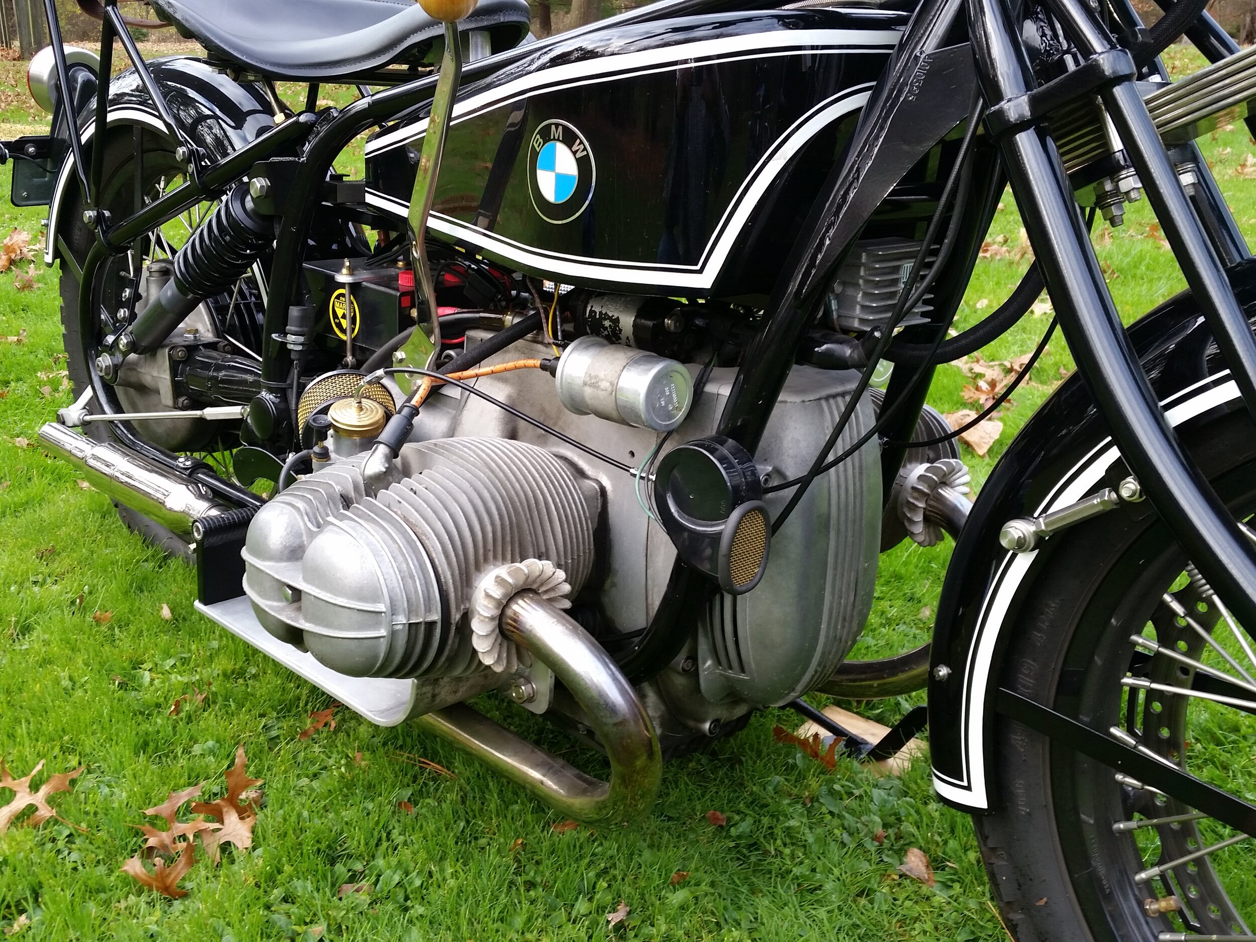
Engine presence, a most important attribute in any motorcycle you ride, is sensed through your hands, eyes and ears. Your ears are taking in the background sound of the engine’s audible pulses making their way down the curves of the exhaust pipes and through the short, but heavily packed shorty mufflers. You can feel these pulses from this beautifully balanced engine just enough to remind you of the reason you are able to effortlessly move down the road at more than a mile every minute. Glancing down you can see the cylinders boldly protruding out from below both sides of the gas tank.
Looking forward you see the beautiful white face of the Motogadget tachometer with its thin red analog needle clearly communicating the engine’s effort.
You stop at a gas station. “What year is that?” you hear from the middle aged lady at the adjacent gas pump. How do you answer that? Stumbling for a moment the only response you can think to say is, “It’s a motorcycle I built to look like a 1920s era BMW”.
This ride you have been on is what I have been fortunate to have experienced on the 1928 BMW similaria. Let’s back up and see what has led to this moment in time.
2. Background
My name is Bob, I’m 70 years old (in 2020), and I enjoy building and riding motorcycles equally. My home is in Cleveland, Ohio and the cold snowy winters and beautiful summers are completely conducive to that equality.
At my core, I like to make things and inspire others to make things. I can’t help myself. Its somewhere in my genes. I spend an average of about 16 hours a week in my shop: thinking, drawing parts, turning metal on a 1940s South Bend lathe, welding and endlessly filing insignificant little pieces. Each year the odometers on my motorcycles total around 14,000 miles and my lifetime miles are over 375,000. Needless to say, I watch almost no TV.
I am writing this because Mac Kirkpatrick of the Vintage BMW Motorcycle Owners Club was nice enough to ask me to do so when I met him at the 2016 BMW MOA International rally in Hamburg, New York.
This article takes you through my particular process of envisioning the finished product, designing, and building in a chronological fashion. I will be referring mostly to three motorcycles hereafter: the “real R52”, my “donor motorcycle”, and my “similaria”.
When the dust finally settled at the end of this project, 2½ years had passed, 277 sketches and drawings had been made, 257 pieces were fabricated (not including the ones that did not make it to the finished machine), and 910 photos were taken.
3. Vision and Inspiration

Some years ago, my friend Chris Hitchcock gave me a paperweight made of solid clear plastic with a 3-dimensional laser etched image inside it of the original 1923 BMW R32. It sat on my desk at my office for three years. I was building a 1914 Harley-Davidson similaria at the time. I couldn’t help but notice the R23’s very unique features, especially that gas tank. I kept asking myself, “How would I make something like that?” I own my late sister’s 1976 R75/6 and would go to the garage on occasion and start imagining how to make the R32 from a bike like that. Next thing you know, I had purchased a donor motorcycle, a 1974 BMW R75/6.
4. My 4 Guiding Lights
Whenever I start a project of any kind, I like to analyze the following: Mission, Goals, Resources needed, and Feedback on ideas and progress. My MISSION was to make a similaria motorcycle that was at the intersection of form and function, where great attention would be paid to the details in every part. Antique motorcycles have an elegant look of gracefulness and simplicity, where nothing is hidden and every part has a function. The eye picks up the distinctive colors of brass, copper, aluminum, and nickel. My goal was to make a similar motorcycle with that old look, but capable of running continuously at 70 MPH, with good brakes, good lighting, enough electrical power to use heated clothing, and “good to go” for the next 20,000 miles.
My GOALS were to go to the next level of fabricating difficulty from my last project (1914 Harley-Davidson “similaria”). This would mean making all or part of the frame. I had fabricated a steel gas tank on the Harley-Davidson, so on the BMW an additional goal was to make an aluminum gas tank that would require some hand forming around some sort of a wood form, or “buck” as they call it.
What RESOURCES would be needed? I have a lathe, small milling machine, TIG welder, and other needed shop tools. What I needed was time, money, raw materials, someone to weld an aluminum gas tank (I can weld but huummm, 5 gallons of gasoline sitting between my legs while I’m going 70 MPH… better let someone else weld that), and other service providers for painting, powder coating, plating, and pin striping.
FEEDBACK on some of my ideas came from friends Ray Shaw and Doug Horner. Feedback on how I was doing time wise came from a time line schedule monitored regularly. Often I needed to make adjustments with time frames and add new activities.
Two and a half years was a long time to keep one’s attention, focus, and enthusiasm for one project so I needed these 4 Guiding Lights to keep me going.
5. Vision and Overall Look

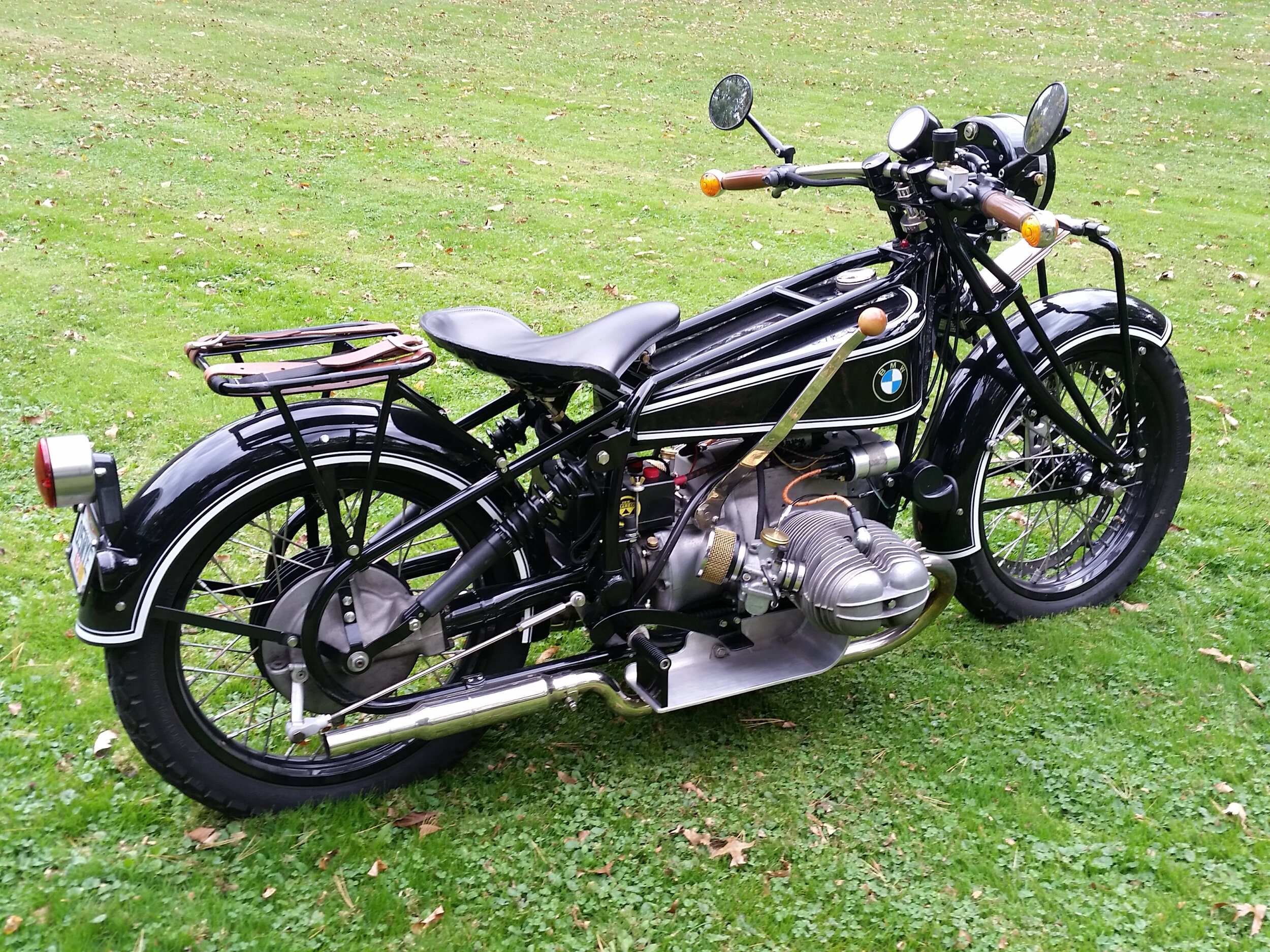
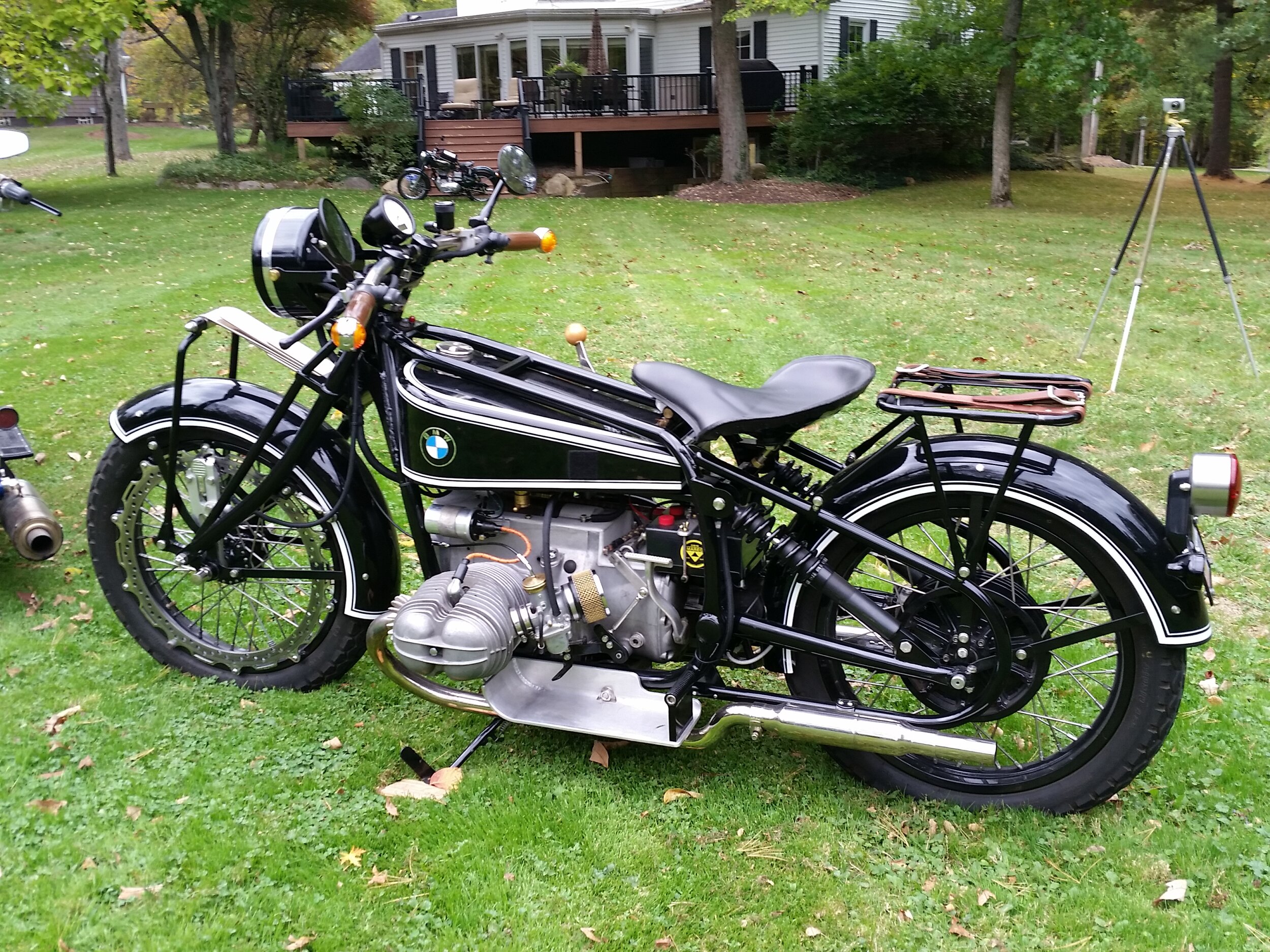
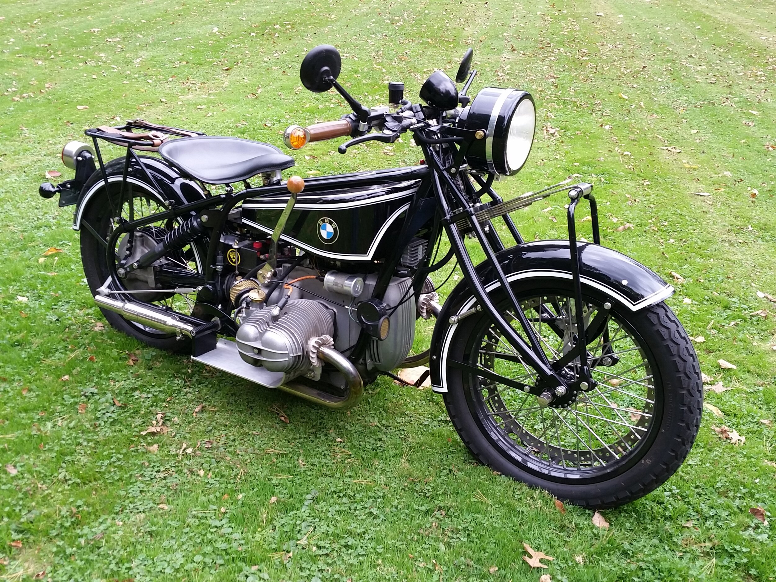
I researched the early BMWs and came to rest on the 1928 R52. That motorcycle had 11 distinctive features that I wanted to include, which were as follows:
Engine: was a horizontally opposed twin with the crankshaft running front to back. It was not tall and there was significant empty air space between the top of the engine and the bottom of the tank. The exhaust pipes ran back, under the footboards (where the small baloney shaped mufflers were placed) and then back to the distinctive fish tail shaped exits. Because the real R52 was a flat head design, the cylinder heads were flat with distinctive cooling fins.
Frame: had two distinct features: the two parallel top tubes OVER THE TOP of the gas tank and the rear hard tail frame had a distinctive loop shape.
Gas tank: was unlike anything I had seen before with its flat top and bottom being separated by the wedge shape of the side panels.
Front end: had leaf spring front suspension.
Wheels and tires: had large diameter rims with thin tires.
Fenders: were distinctive with their chopped-off ends.
Headlight: was not conical shaped like so many bikes, but had a cylindrical shape.
Footboards: were mostly flat, but had a rounded up curvature in the front which partly wrapped around to the side.
Handlebars: had a flat design, and when viewed from above, they had a gentle curve bringing the hand grips closer to the rider.
Hand shift: had a long arm that came up the right side of the motorcycle.
Finish: had no chrome but had nickel, raw aluminum, brass, copper, and a unique pin striped design.
From these observations, drawings were made of the entire motorcycle but modified to what I wanted to achieve. My drawing tool of choice for this was Paint, a software that came on my computer many years ago and met my parameters for good software: no additional expense, I did not have to load it, does the basics, and does them easily. You may prefer Photo Shop or the simple cut-(with scissors)-tape-and-markers technique using real paper.
Using these drawings I could look ahead and determine the challenges that this design would bring, and start to solve them. It was much easier to discover and solve an issue “on paper” rather than to be surprised by problems that result in having to cut off, scrap, and remake metal parts.
For example, this was where it was discovered, among other things, that the motor was mounted on a 6 degree angle in the donor motorcycle. I never realized this because the angled top of the engine is hidden under the gas tank, the oil pan’s bottom is wedge shaped making its bottom horizontal, and the engine badges are mounted level, at a 6 degree angle to the engine. This was definitely not the look of the real R52 which had its engine mounted in the level position (because there was little/no suspension travel in the front/rear). In order to get the engine level and not add more angle to the engine/drive shaft intersection, visualize rotating the frame and engine by 6 degrees around the rear axle until they are in the horizontal plane. To achieve this, the front forks needed to be shortened or the steering neck needed to be raised. I had chosen my forks (Kiwi leaf spring) so their length was a given and the solution would be to lift the steering neck by lengthening the front down tubes. For the simplicity of this discussion at this point I have left out the consideration of the change in rake and trail of the forks.


Note how much the rear wheel had to be lifted to put the engine in a level plane.
6. Designing and Building
As the thinking began for the design and construction of the motorcycle, there were some primary things to consider. Early on there was the need to solidify the decision on the use of the project motorcycle. Would it be a trailer queen, rolled out of the garage occasionally, taken to a show in an enclosed trailer and never started up? Or would it be an occasional rider, getting a 40 mile ride now and again? My use was a third option, a rider, getting ridden 1,000 – 2,000 miles a year including some multiple day trips.
Thought was also given to the sequence of construction. Sometimes there was a necessary sequence, sometimes there is an interdependency of items which must be solved simultaneously. For an example of the latter, if you were planning to put all your electrical connections in the headlight bucket along with relays and fuses, you had better know their sizes and layout so you pick an appropriately sized headlight bucket.
Also there was the need to remember that the motorcycle I was using as a starting point was a functioning system, if change was made on one item then something else was bound to change. There were many inter-dependent variables in the equation. The challenge was to know the other variables. I had given an example above when mentioning the rake and trail would change as a result of changes made to the frame’s steering neck when I wanted the engine to lay more horizontally.
7. Engine
The engine, for me is the heart of it all. After all, what is the first part of the word “motorcycle”? For me to own a motorcycle, it has to have ENGINE PRESENCE. I define this as follows: when riding, I have to be able to do at least 2 of the following when riding: SEE the engine, FEEL the engine (to some degree), and HEAR the engine (also to some degree).
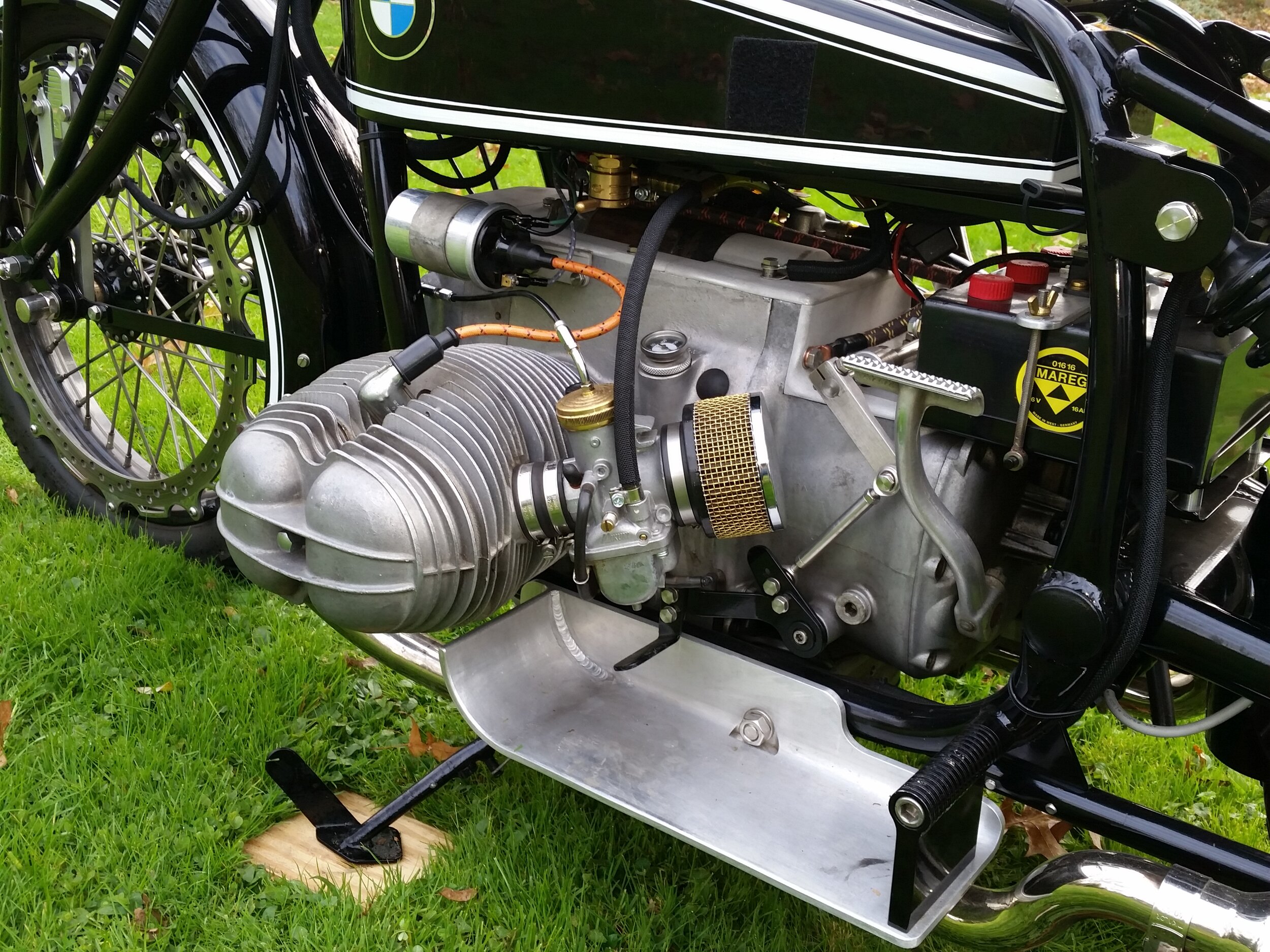
There were four characteristics of the engine of the R 75 that needed to be changed to give the look I was after. 1. The engine and transmission were much too tall, and massive looking. 2. They were not horizontally mounted as previously mentioned. 3. The CV carburetor just did not look right with its large mushroom shaped top. 4. The cylinder head area was defined by the rounded valve cover contrasting with the R52 with its side valve flathead design with a flat appearance and distinctive cooling fins.

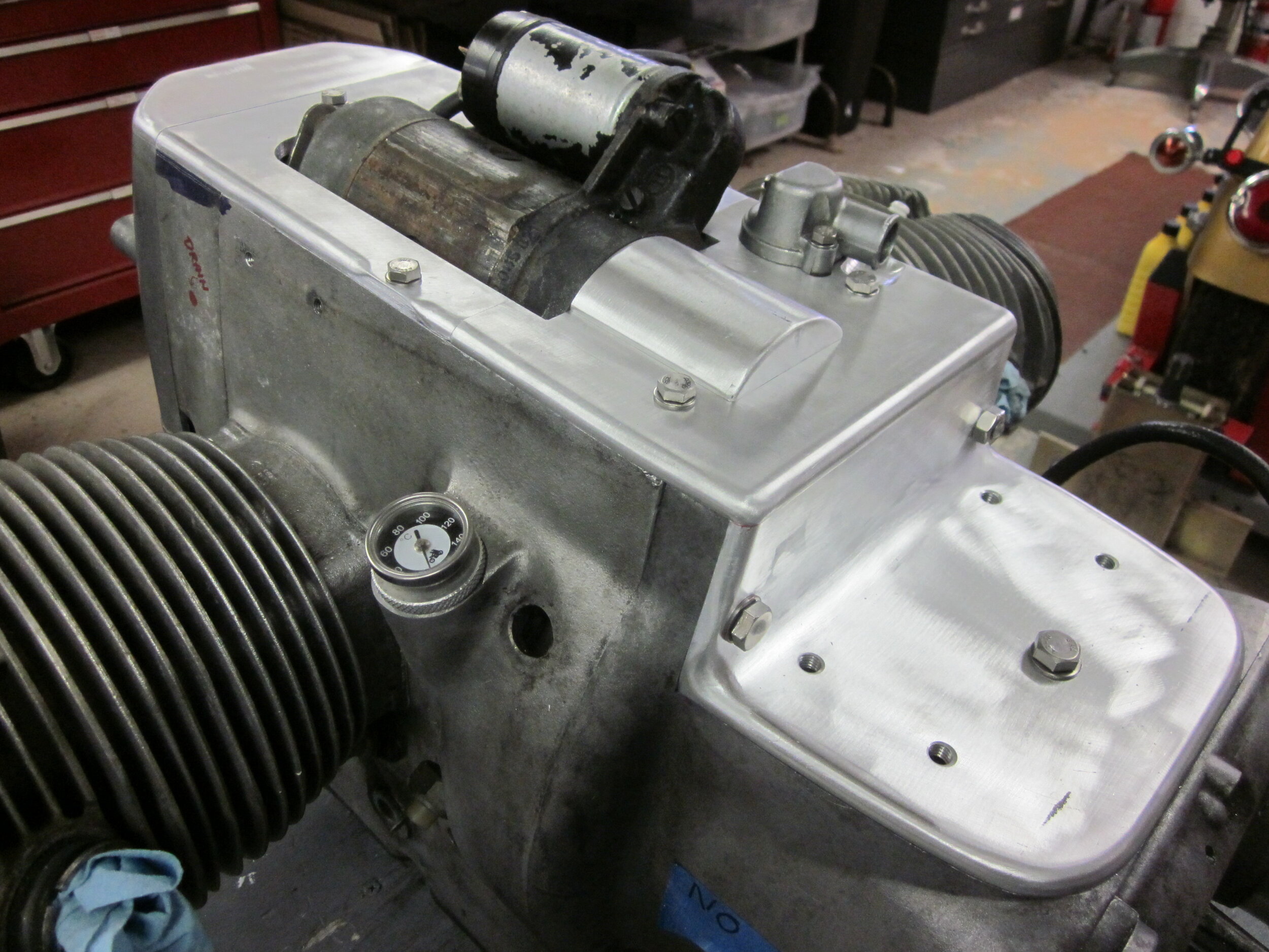
To address the massive look of the engine and tranny, the air cleaner compartment was to be eliminated in favor of small pod type air cleaners on each carburetor. In place of the air cleaner compartment a piece of thick aluminum angle was used, with rounded edges and then sand blasted to look like a casting. For the engine, the large top cover over the starter motor would be eliminated. I wanted to make a flat cover for this area with the same rounded edges and sandblasted look of the air box replacement piece. I would make a cut-out for the starter to stick through, and fabricate a hump in the cover to seal the clutch compartment against water entering.

But the upper portions of the timing case cover and front engine cover would have be cut off in order to extend this flat cover. This was what I did. Yes, I see you purists in the back row cringing at the thought that I would actually CUT these pieces off. Sorry. The front engine cover would also have its own separate but visually contiguous flat top which was welded to the front cover.
But what about keeping water out of the starter cavity and the front engine compartment that housed the diode board and alternator? I knew that water would eventually enter into these areas in a big rain downpour. For the starter motor cavity I knew the starter motor was waterproof because it is the same Bosch unit mounted on the outside of my 1975 Moto Guzzi’s engine. But just to be sure water would not create a pool of water in the starter cavity, I enlarged the two existing holes in the engine case and drilled four more, two on each side.
If water leaked into the front engine compartment, it would no longer cause arcing at the brushes of the alternator because I was replacing the stock alternator with a Euro Motoelectrics® brushless unit which uses permanent magnets, eliminating the brushes and their commutator. How did I know these theories and assumptions of water entry were correct? Not wanting to find out somewhere out on the road, far, far from home in a driving rain storm, after my build I ran a garden hose, water pouring out, directly into the gap around the starter motor and the engine continued to run.
And what about maintaining internal air flow (the need evidenced by the presence of air intake cutouts in the front of the front engine cover, the flow holes in the timing case cover and the large rubber air exit boot in the engine top piece)? What was air flow needed for? I believe mainly for the diode board, but it was no longer needed because I was using the more conventional exterior mounted regulator rectifier. Also some air would still flow out of the opening around the starter motor to cool the alternator.
It’s tempting to apologize for such a hideous amount of detail about this, but there are a lot of things one needs to think about when disrupting the functioning system of a stock motorcycle.
In building the engine, I did not clean the block, other than giving it a good scrubbing with very soapy water, because of my paranoia about any kind of abrasive grit in blasting media. I also liked the patina of not-so-clean aluminum, giving the motorcycle a more genuine look with the possibility that it might be mistaken for an actual “original”.
Replacement of the Bing carburetor with its mushroom shaped top was taken care of by Northeast Cycle Works who supplied the Mikuni carburetor conversion to give a more period correct look. They were knowledgeable about fitting these carburetors to 1970s BMWs. They also supplied compatible throttle cables along with recommendations on jetting. I used a K&N pod filter and then covered the filter media with brass screening. I cut the screen to size and, to keep the wires on the edges from coming apart, I soldered every one of the wires on the edges, all 408 of them! Refer to the picture of the brass screen on page 3.
The exhaust pipes and mufflers were not built until the floorboards were designed and fabricated because the exhaust pipes had to work around them. But since we are on the subject of the engine, I will talk about them here. I started with the donor bike’s header pipes, cut the cross-over pipe stub off and filled the resulting holes. The curvature of the pipes had to be adjusted slightly. In two spots on each pipe, a cut was made 80% of the way through the pipe, then it was pulled together and welded up.
The mufflers were placed behind the footboards on my similaria and not under them like the real R52 because the similaria had rear suspension. When the shocks were fully compressed, there was concern about sufficient ground clearance for the mufflers under the footboards.
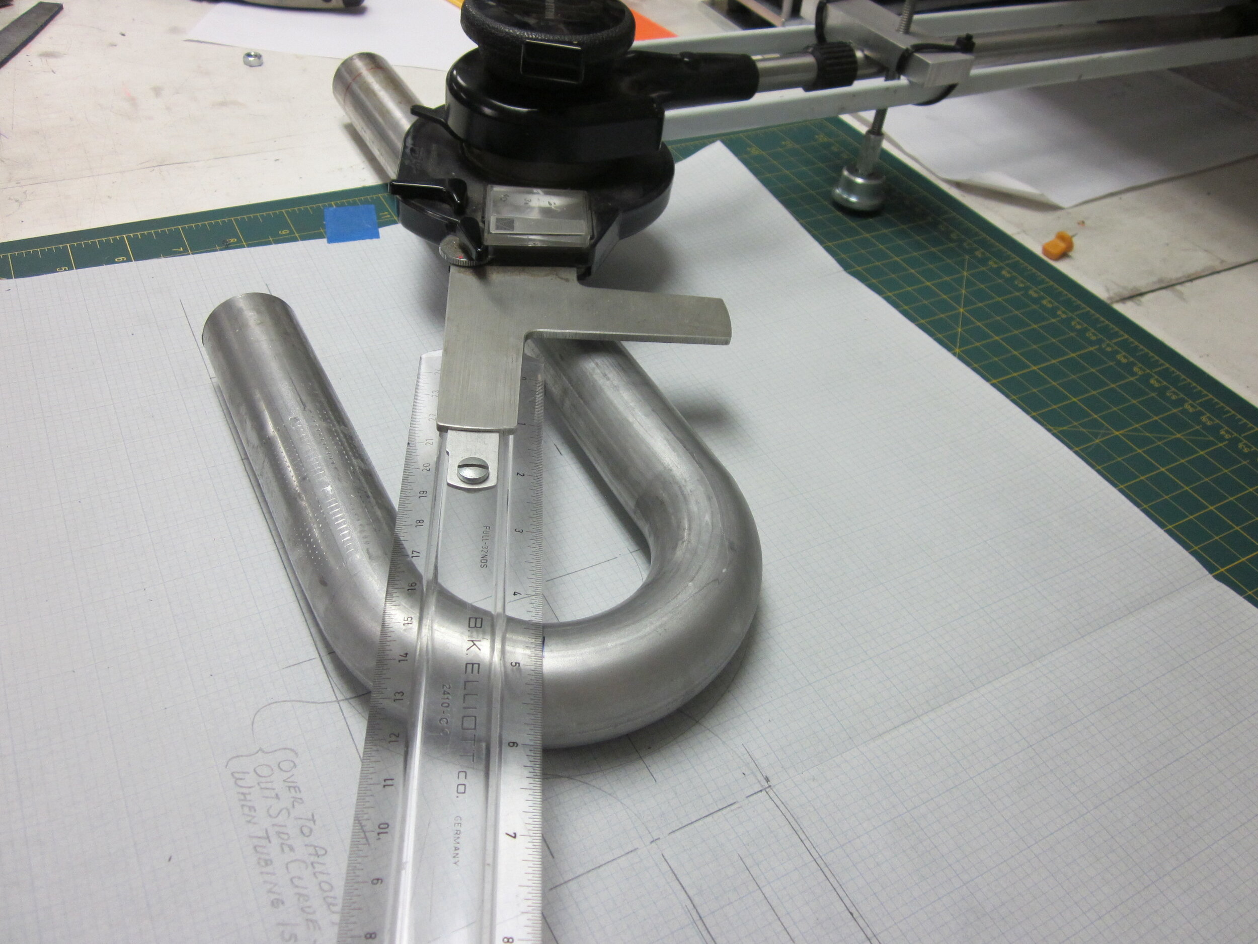

So the mufflers were placed rearward of the footboards and an “S” bend added to the exhaust pipes to raise their elevation. How does one make an “S” bend? Companies like Summit Racing sell “J” bends. They come in a wide range of pipe diameters which are indispensable for cutting sections out of to fabricate needed shapes, which is what I did.
The desired look for the mufflers consisted of a relatively short length, with the same 1½ inch ID (inside diameter) pipe connections at each end, baffles that had packing around them (to give a softer, more mellow tone), and were able to be repacked. Such items seemed to be made of “un-obtainium”. What was available was a shorty muffler with a 2½ inch diameter body, 1½ inch ID inlet, 1¾ inch ID outlet, and the 1½ inch diameter baffle was removable, but could only be wrapped with a ¼ of packing due to the restriction of the ID of the outlet pipe that the baffle was installed through. I just could not stand either the look of the 1¾ inch outlet pipe or the thought that the baffle could not be adequately packed around. Solution: purchase 4 mufflers, cut them all in half, keep only the 4 halves with the 1½ inch ID ends, make a sleeve to fit inside the 2½ inch body so two of the halves could be joined together (and later separated for repacking), and fabricate baffles out of 1¼ inch diameter perforated stainless steel tubing that could now be wrapped (and later rewrapped) with 5/8 inch of packing.

The real R52 was a flat head design with cooling fins. My donor R75/6 had overhead valves so the “tops” of the cylinders were actually valve covers. A prototype of valve covers was made with a flat head look (if only in my mind) out of balsa wood. Since I was unsure of what spacing between the cooling fins would look best, two different spacings were included on the one prototype.
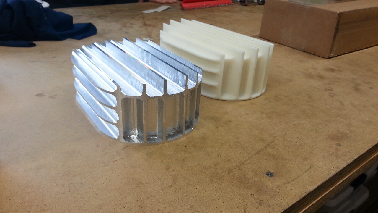
To make a long story short (a technique that I seldom utilize), the students at The Gow School, located outside Buffalo, NY made a CAD drawing of it, printed it on their 3D printer in plastic. They then converted this drawing file to a CNC machine language and made the aluminum parts on their newly acquired large 3 axis Haas CNC milling machine. This was an amazing achievement for the staff and students because this was all new to them and they had no prior experience working with either this technology or CNC machinery.
Afterward, a friend working with a local manufacturer fine-tuned the design and manufacturing to produce the final two valve covers.
I then sandblasted them so their surface had the rough look more like a casting.
8. Frame
The frame’s function is to hold together the engine, two wheels and provide a place for the rider to sit and control. With the engine figured out, I now needed a frame to hold it, keeping in mind how the wheels would be connected and supported. Each time I build a motorcycle, my desire is to go to another level of fabrication and do something I have not done before. Building a structural part of the frame was one of my goals here.
The BMW’s frame, when viewed from the side, is a basic rectangle (similar to the famous Norton “Featherbed” frame). So I will be referring to the 4 sections: front, top, back, and lower sections. I wanted to maintain, as a unit, the engine, its drive shaft, the rear swing arm with the rear drive hub. To keep all this together in perfect alignment, I wanted to keep all these pieces attached to the lower and back sections of the original frame, tying together the engine and the back section that holds the swing arm mounts.
Now, how about the front portion of the frame, up to and including the steering head? Referring back to my discussion about wanting the engine to be in a level plane, I knew there would be modifications needed to accommodate the front section I would be using. This front section would establish the location of the steering head, relative to the rest of the frame. My calculations told me the front down tubes had to be lengthened with spacers to accommodate the height of the leaf spring front end and the steering head had to be tilted back to achieve the desired rake and trail.
Choice of rake and trail is a long and involved discussion and there is much information on the internet. Suffice it to say, I decided on 30 degrees of rake and 3.5 inches of trail.
As for the top section of the frame, the plan was to cut out the one large tube on the donor bike frame (that connected the two back sections to the front steering head) and replace it with two parallel tubes. These tubes would run ON TOP of the future gas tank to achieve one of those distinctive features.

I also wanted the distinctive feature of the rear loop on the frame. The real R52 had it on one side only because the rear drive was on the other side but I chose to have this feature on both sides. This meant I could not have conventional rear shocks placed in the standard vertical position because there was now no frame to attach the top of the shocks to.
To that end, one thing my 1914 Harley similaria taught me (a hard tail that I have ridden over 10,000 miles) was that when they started putting rear suspension on vehicles, they were on to something! I’m going to stick my neck out here and make a prediction that I think it is here to stay. So I thought that if rear shocks were put inside the loop, they would be much less visible and the loop would be more visible to the eye. I figured I could connect the bottom eye of the shock to the stock location and the top could be tilted forward to intersect with the top of the rear frame section. This put the shock 30 degrees to the horizon and in such a position that a 30-60-90 triangle was formed by the three points: the bottom eye, the top eye and the swing arm pivot.

Referring back to geometry class, physics, and vector analysis, I am sure you remember that side O is ½ the length of side H. This means two things. First, if you want 3 in. of vertical axle movement, the shock only moves approximately 1 ½ inches. Secondly, a 300 pound force vertically on the axle transmits a 600 pound load on the shock. This, and the fact I now needed a 15 in. length shock rather than the 13.5 inch stock shock, meant I had to find someone to build a custom set of shocks. Enter Works Performance. They built these with the needed travel and stiffness and added a very reasonable engineering fee.
With these frame issues figured out conceptually, how was I going to hold all these pieces while I cut up the donor bike’s frame, measure and fit the new sections? I needed to build some sort of a fixture to hold the frame pieces in alignment while I cut the top section out and while the front section was cut off awaiting modification. The resources used were my wooden work table, Unistrut®, turnbuckles & wire, and a digital level/angle gauge.
The table was a decent platform to attach my fixture to hold the frame. Was it perfectly straight and level? No. But did it need to be? While I did do my best to get the table aligned, all that is important is that the fixture and frame I am building on the table be level, straight and vertical in the needed areas. The digital level/angle gauge was my tool of choice to assure perfect alignment.

A tensioned wire was placed as close to level as I could get it, to function as the centerline of the frame from which future measurements would be made.
Unistrut® and their various clamps were used to fabricate a fixture. Turnbuckles and wires were utilized, along with the digital level/angle device, to “tune” the frame into perfect alignment.
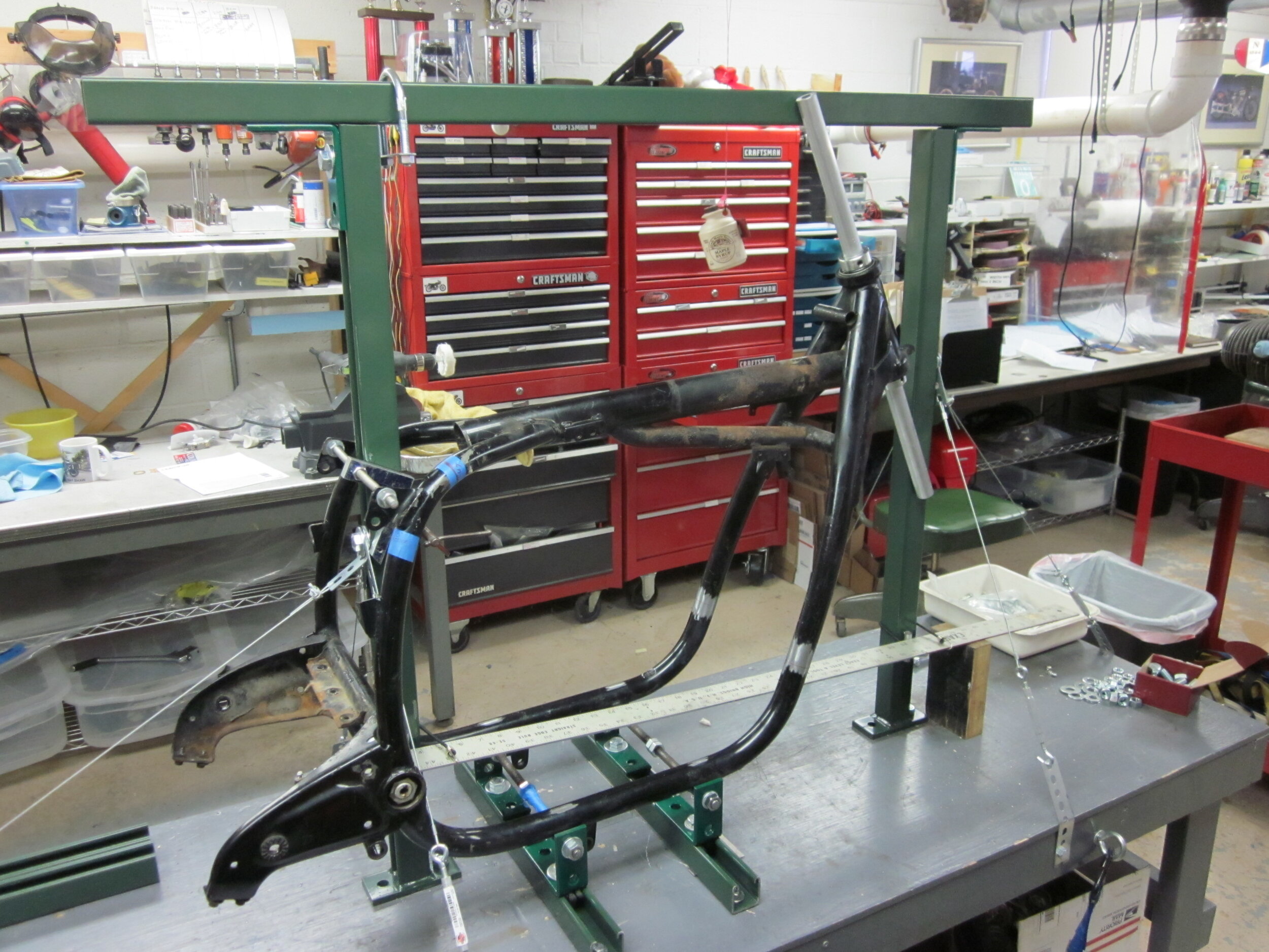
The stock frame was then mounted to the fixture. The top and front sections were cut out. Taking the front section, I secured the upper and lower steering head bearings to a piece of aluminum rod that ran through the steering head.

As the picture shows, this assembly was attached to the fixture in its proper location. It was critical to perform that work, and the following top tubes construction, with the upmost accuracy and precision so that the bike would handle well on the road.
Next was the process of fabricating the two filler pieces to the down tubes and welding them in place. The picture shows one filler piece in place.

This was followed by fabricating the two top tubes with their bends and then the very long and tedious process of joining the two top tubes to the steering head at the front and to the frame tubes at the back. This was by far the most complex “fitting” work of the whole project. First, where the rear section transitions to the top tubes, the cuts in the stock frame had to be in an exact location and at the exact angle. Secondly, at the front of the top tubes, there is a complex compound connection into the round steering neck. All this had to be done assuring the two top tubes remain parallel. If any one of these four joining surfaces were cut or filed 1/32 in. too much, the top tubes would be out of alignment with each other. Fortunately the process produced no profanity…. that I can remember. Have I mentioned what a bad memory I have?
9. Gas tank

When designing the gas tank, I knew the shape of the tank I was looking for, but how was it to be made and how was it to be attached to the motorcycle?
A prototype tank was made Styrofoam®. This meant it could be visualized and questions would be answered like what its volume would be. Being a rider, I wanted a gas tank with a minimum of 4 gallons. How will it be supported? How can it be removed? Oh yeah, the foam prototype let me realize that the cool gas cap stuck up so far that the tank could not simply slide horizontally out of the frame. Oh and look, the tank could only be removed from one side because the hand shift will be on the other. I guess that meant the gas petcock has to be on the other side because it would not slide past my proposed support rails under the tank. On and on the questions came, and the answers were figured out.
The gas tank was to be aluminum and the engine (sorry to say) does vibrate somewhat. Aluminum fatigues and cracks over time when exposed to vibration. My solution was to have the tank rest on two parallel inverted beams running front to back. The tops of the beams where they contacted the tank were to be covered with 1/8 inch thick soft silicone rubber. The tank had 4 mounting points, 2 on each beam.

The tank’s mounting points were top hat shaped pieces, made from aluminum. The brim of the hat was 2 inches in diameter and the hat portion was 1 in. diameter. There were threaded holes partly bored through the bottom of the top hat. 1 in. diameter holes were drilled into the bottom of the tank and the top hats are fit up through the hole and welded along the edge of the brim. Bolts were then placed up through holes in the beams into the top hats to secure the tank. There was thread lock compound on the bolts so they did not have to be fully tightened. That means the tank is partially isolated from the engine vibration.
Building the tank was a lot of fun………well mostly. Using the foam prototype, a wooden form (called a “buck”) was made.
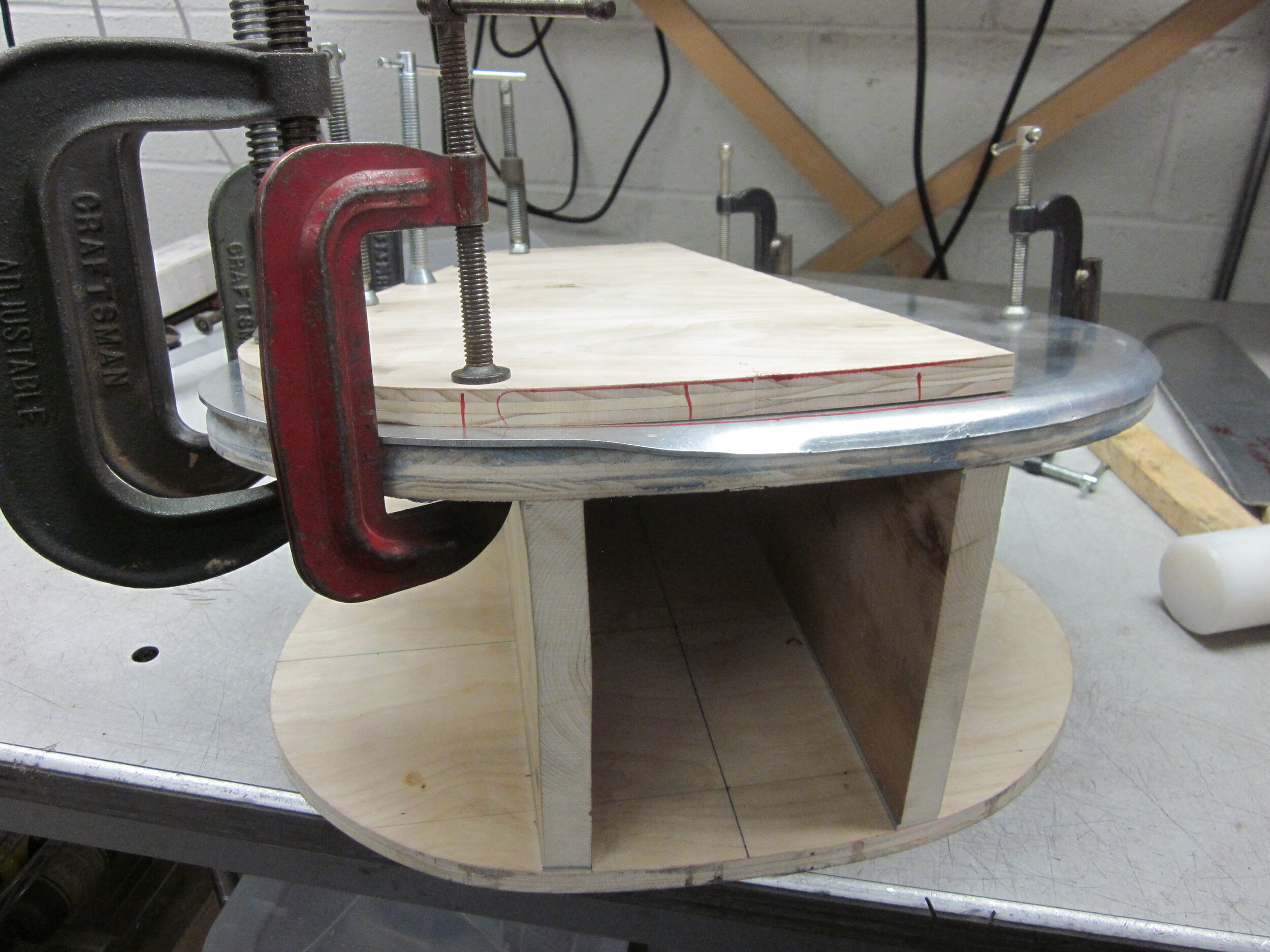
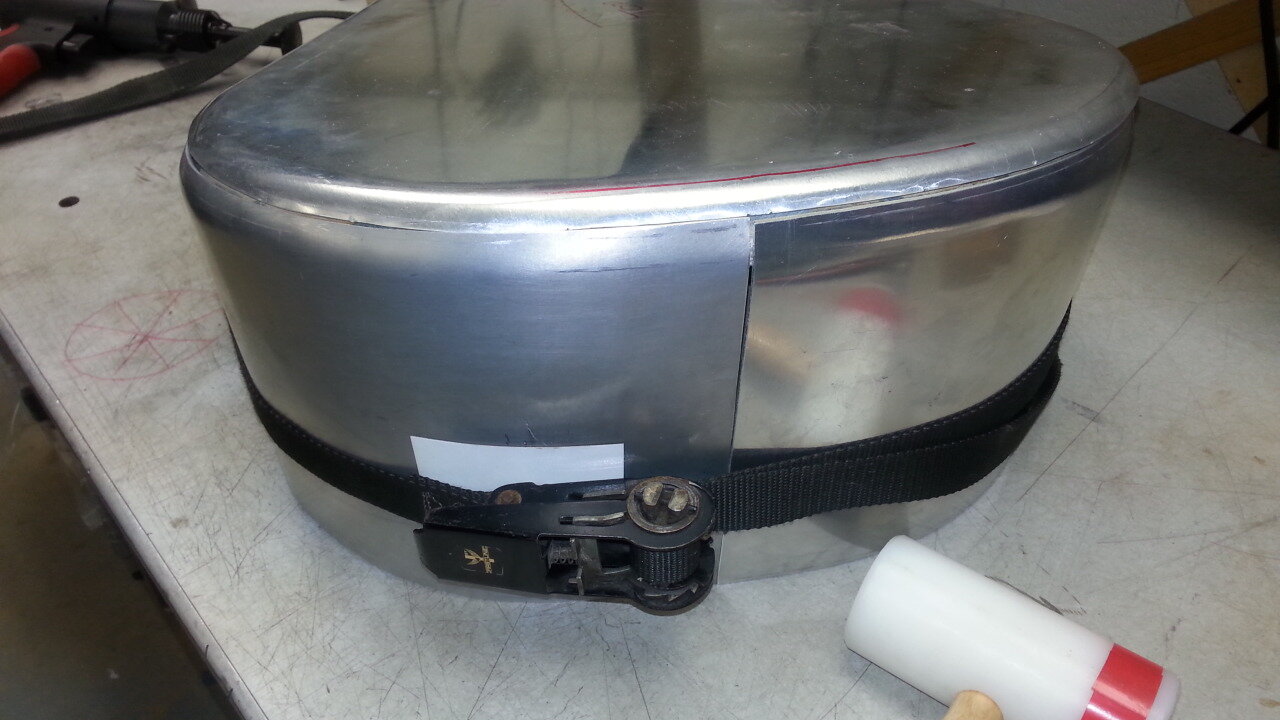

The edges of the top of the buck were rounded using a router. Then a large piece of 3003 aluminum, .090 inch thick, was cut to shape for the top. The edges were annealed and then hand beaten half way around the rounded edges. The right, front and left sides followed the same process (well, except for the part where I over heated one of the pieces when annealing it and melted a hole right through one panel). The bottom (made of .125 inch thick aluminum) and back piece were fit. Then the front angled section was cut out and a filler plate made.
After a bung for the fuel petcock and gas cap neck were welded in place, hours of filing and sanding ensued to hide the welded seams.
10. Front End: Suspension
At the front end I wanted the design to include leaf spring suspension because that is what was on the real R52 and it was one of the 11 distinctive features to be included. A Kiwi front end was chosen.
I had already thought through using this when I was in the frame design and fabricating phase so the placement and angle of the steering head was now set.
I did however have the issue of the donor motorcycle steering head bearings being metric but the Kiwi took SAE bearings. Fortunately the OD of the SAE stem was smaller than the ID of the metric roller bearings. This meant sleeves could be made to fill the gap between the stem and the inner races.
11. Wheels and Brakes
I wanted the look of large diameter wheels and thin tires. Also desired was the use of the same size tire on the front wheel and the rear wheel because that was generally the case back in the 1920s. This would be beneficial when traveling because only one spare inner tube would be needed, saving weight and space.
Which wheel to be used needed to be figured out first. Since the leaf spring front was fairly open, nonrestrictive and simple, the rear wheel needed to be thought through first.
The rear tire had to run clear of the cross member of the swing arm. If the diameter of wheel and tire was too big, there was the need to either make a cut-out in the cross member of the swing arm or the two sides of the swing arm would have to be extended. This being a shaft drive, extending would be very difficult. Since the stock rear wheel was 18”, I figured my only choice was an 18” wheel/tire set up because of my assumption that a 19” wheel/tire would have an increased diameter and not fit. I never thought to measure a 19” wheel/tire. (Really Bob?!) So the decision was made to use 18” front and rear and to use black powder coated aluminum rims. Buchanan’s made stainless steel spokes to fit this arrangement.
It was now time to decide on a front brake. The small diameter front drum brake on the real R-52 was really small. How small was it? It was so small that I would call it more of a slowing device rather than a brake. My experience with these brakes is that they did not meet my requirements for adequately slowing down a motorcycle. (My experience even included a 230 mm (xxx inch diameter), double sided, 4 leading shoe brake.) Wanting this motorcycle to be a rider, and a safe one at that, I knew I liked disc brakes. A traditional disc brake would be very functional and I was prepared to use one (or two small diameter ones). I also knew some antique motorcycles had no front brake. So I decided on a more radical approach and had HD Wheel fabricate a perimeter disc brake, like the style Erik Buell used on his motorcycles. This left only the small spindle at the center of the wheel giving, at first glance, the impression of an antique motorcycle with no front brake at all. Cool.
For this style of brake the caliper is not mounted to the fork leg but to a carrier arm that attaches to the axle.

A bronze bushing on the axle was machined to mount it to. I fabricated the link that attached to the fork leg. This link is a forked type which attached to both sides of the caliper carrying arm rather than attaching to just one side. This greatly reduces the twisting force on the caliper carrying arm caused by the caliper’s brake pads not being in the same plane as the arm which has the effect of very uneven brake pad ware. And why do I think I know so much about this? Well, I made the mistake of a one sided attachment on a previously build and had very uneven brake pad ware due to the twisting action.
While we are on the subject of the wheels, tires and brakes, I will jump ahead in the story for a minute. Once I had enough of the motorcycle built to be able to ride, I went out for a series of what I call “beta test rides”. The more I looked at the motorcycle the more I did not like the 18” wheels and tires. They just did not have a large enough diameter. At some point I wondered how much of a gap would I have to cut in the rear edge of the swing arm’s cross member to be able to fit a 19” tire. Ruler in hand I made the measurements only to find the answer was 0, zero, nada. Nothing had to be removed and the 19” wheel/tires could fit at the rear and therefore the front also. Forgetting the time I had wasted, oops I mean invested, I knew this meant buying a second new custom made front rim-spindle-spokes, brake, caliper support arm, a second rear rim, spokes and two tires and tubes. I have learned in the past that with all the time, money, and effort that go into one of these builds, EVERYTHING has to be as correct as I can make it to my eye and in my mind. As soon as I know something is not right, I stop immediately and if possible, correct it. So I made the changes. Anyone want to buy a beautiful 18” front wheel with a rim and perimeter brake, complete with caliper and a Dunlop K81 (TT100) tire? Oh yeah, I also have the rear wheel rim and tire!
12. Fenders
The look I wanted for the fender was one that fit closely to the tire. Many early antique motorcycles had no suspension so the fenders could be fit that way. As suspension was introduced in the late teens and 1920s (like on the real R52) the fenders were often affixed to the nonmoving part of the forks or frame so there needed to be a considerable gap between the top of the tire and the underside of the fender, so the wheel could travel up and not hit the fender. I just don’t like that look.
So I designed a system where the front fender stays attached to a bronze bushings on each side of the axle. As the wheel and its axle move up and down, the fender travels with it. To keep the fender and fender stay assembly from just rotating around the axle and hitting the ground, I fabricated stainless steel turnbuckle style braces for each side of the fender, anchoring it to the fork leg but allowing it to swing. To assure precise alignment of both sides, each turnbuckle has a right and a left hand threaded end for the connecting rod ends.
The rear fender had similar issues of traveling with the rear wheel so it’s attached to the swing arm in several places.
Both fenders were steel and were cut from blanks from Wild Card’s Long Boy Front Fenders. The front and rear ends of both fenders have a rather straight cut to be similar to the real R52.
13. Headlight
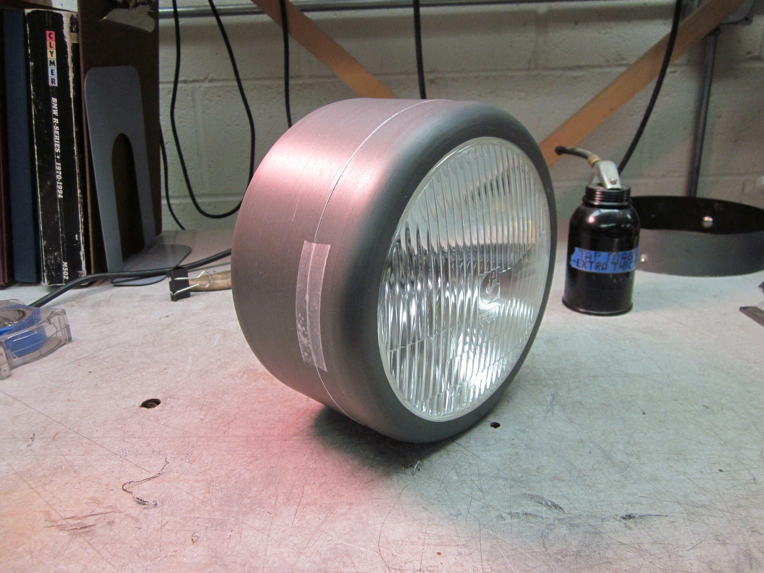
I was confident I could make the cylindrical shape the sides of the headlight, but what about the rounded corners at the transition from the sides to the front and back of the light? Off to a Target Department store I went with a tape measure in hand and the desired 8 inch diameter in mind. Up and down the isles I roamed. Hardware? Nothing. Homewares? Nope, nothing. School supplies? Nothing. Lady’s underwear? I think I can skip that one. Camping? Nothing. Cookware? Hey, what about that 8 inch KitchenAid® aluminum saucepan staring me right in the face? It’s complete with a beautifully rounded transition between its sides and bottom. I’ll take two of these please. Yes, I spent $99.98 for these two, but that purchase, even including the time to go to the store, saved me a lot of time building.
I incorporated a smaller cylindrical section in the back of the headlight similar to the real R52. Thinking I was on to something with my “cookware” solution for the headlight’s main body, I cut a hole in the back of the headlight and inserted a 5 inch diameter wedding cake pan.
The discussion about the headlight’s electronic internals is found later in the sections about electrical wiring and wiring diagrams.
14. Footboards
These footboards were another important distinctive feature look of the real R52 which was comprised of a flat surface for the foot and turned up on the front edge.

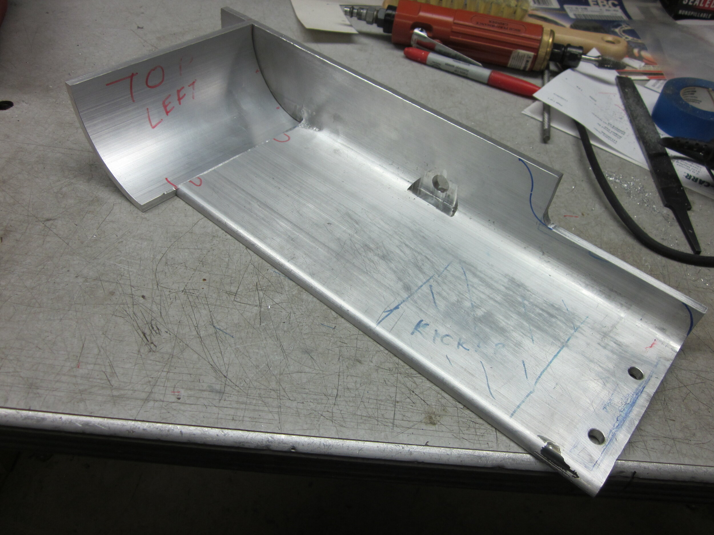
My design included getting a 6 foot long piece of aluminum angle, 6” x 6” legs and ¼ “ thick, a substantial piece of metal. Two 14” pieces would be cut, one for each footboard. On each side, one of the 6” sides was to be cut to approximately 2” and that became the vertical face which attached to the frame using lengthened engine mounting bolts. I figured out how to make the nose turn up on the front edge, but could not figure out how to make it continue around to the side. The front edge would be accomplished by starting with a 6” long piece of aluminum pipe, 5” OD with a ¼” thick wall. Looking at the end of this piece imagine cutting out a quarter section. That piece would be welded on the front edge of the footboard.
The building went as designed until the human aspect introduced, AKA the rider. Try to envision sitting on the seat, with your feet a short distance directly below the seat. Sitting in that position, the bottoms of your feet want to be angled down and forward, not horizontal. Even harder, or in my case impossible, I could not further rotate the foot at the ankle to lift my toes to get on top of the shift lever or brake pedal.
So, looking at picture of the finished product you can see I made an elevated foot peg at the back of the footboard (in black to hide it a bit visually from the foot board) to rest my feet on and be able to get my toes onto the pedals within the limited space under the carburetors.
15. Handlebars
As mentioned before, I wanted to keep the real R52’s look of a basically flat design, and when viewed from above, they had a gentle curve bringing the hand grips closer to the rider. The mounting brackets accommodated 1 in. bars but I wanted to use the stock switchgear which goes on 22mm bars (almost 7/8 in.).

The solution was to utilize a rolling type bender to form the 1 in tubing and then weld in a 10 in. long piece of 7/8 in. tubing at each end.
16. Hand Shift
After the seating and handlebar position was established, and I knew where my right hand would naturally be able to move the shifter back and forth, a prototype of foam board and wire was made to establish the design to connect the right hand’s movement to the left side shift lever on the engine. A cross shaft would be used, mounted in two self-aligning bronze bearing pillow blocks mounted on top of the transmission.
I wanted the hand shift lever to be made of aluminum because it would be long and positioned at the 2 o’clock position. This meant there would be a constant rotational force on the cross shaft and therefore the transmission’s shift mechanism. Wanting to minimize that, lightweight aluminum was chosen. Much to my delight my plating company informed me that they could nickel plate (therefore chrome if any of you want it) aluminum. Who Knew?
A short little “cheater” foot shift lever is included in the fabrication to allow the occasional need to shift quickly (that’s BMW quickly) when needed in certain traffic conditions.
17. Combination Tachometer/Speedometer
I saw a Motogadget instrument at a motorcycle trade show when I was planning this project and said “This motorcycle has to have one of those”.
I wanted to have just one instrument on the handlebars so a combination tachometer and speedometer was chosen. I preferred one with an analog needle for the speedometer and the digital display window for the tachometer. However, I could only find a metric speedometer display which had numbers up to 200 KPH. It just seemed wrong to have such high numbers displayed on a 1928 machine. OK, Ernst Henne did go 216 KPH run in 1929, but that was a world record! So I opted for the tachometer analog needle with a digital speedometer window.
This Motogadget is an amazing device with a digital window in the face that toggles through 16 different functions and data. Among these 16 are odometer (able to be set to the ending mileage of the donor bike and engine) trip odometer, speedometer, tachometer, voltage at the battery, etc.
There were 16 wires that can be connected into the motorcycle wiring harness. My machine utilized 11 of them. There were vivid instructions included with the Motogadget. I must say that it was important to have a basic knowledge of electrical circuits. One of the very important analyses you needed to be able to perform was to determine, at different points in the bike’s wiring, what the polarity of each of the wires was. Other than the alternator’s AC wires up to the rectifier (diode board), the system was basically a DC system.
18. Electrical
Being a rider I wanted certain changes to the donor motorcycle’s electrical components. I wanted to be able to run an H4 halogen headlight, electrically heated clothing, a GPS/phone, etc. This meant a high-output alternator. My choice was the Euro Motoelectrics® unit that puts out up to 450 watts with its brushless design (AKA low maintenance) and a modern regulator/rectifier (replacing the diode board). I kept track of my modifications by continually updating the wiring diagram.
I am a firm believer in the Odyssey® AGM batteries. I use them in all my other motorcycles if they can fit. They are expensive BUT I have replaced them after 10 years because it seemed like the right time, NOT because they didn’t work. Like most other AGM batteries they can be mounted on their side so that gives great flexibility in putting them in different locations. Model PC680 was used on the R52 similaria. My first choice was to hide it by placing it under the transmission. This gave a less cluttered look and allowed more empty space between the engine and gas tank. This approach was abandoned due to the impracticality of getting to it when I was on the road, should I need to. So on top of the transmission it went and thinking started on how to make it a feature. A plastic case was made to cover its orange exterior, threaded rods with brass wing nuts secured it, Mareg® decals applied (not sure if they were even in business in 1928), and three red caps added (rather than 6 on a 12 volt battery) to give the impression of a 3 cell 6 volt battery. I just HAD to have the red caps with deeply ribbed sides. Where did I get these you probably would not ask? I could not find them anywhere until one day it dawned on me. Every morning I put Half and Half creamer in my coffee from a pint container. I realized the cap on the container was the perfect shape and size for the battery cover. My wife makes art objects out of polymer clay, a soft malleable plastic-like material which hardens when it is heated in a toaster oven. It is available in a plethora of colors. I made a silicone mold of the cap, filled it red polymer clay, baked it and, voila, my first of three faux battery caps.
Good lighting was also very important. The headlight has an H4 halogen bulb, the tail light has 18 LEDs in it, the turn signals were classic BMW items (OK, maybe not back in the 1920s) but with LED festoon style lighting.
Knowing that riding in the rain is inevitable, the electrical connector plugs used throughout the motorcycle (except for the high amperage wires like the 3 alternator leads) were the Deutsch type. These came in 2, 3, 4, 6, 8, and 12 wire plugs, two different colors and appeared to me to be very water resistant.
One can spend a lot of time and money in many different areas of the build, but (in my opinion) you cannot invest too much on the electrical system.
19. Electrical Wiring and Wiring Diagram
This is one of my favorite subjects. It is an area that sets apart the “show” motorcycle from the “rider”. It is another area where attention to detail is so important. It’s like the nerve system in the human body. None of the electrical “organs” of the bike operate without the wiring system. One goof-up can lead to a melting wire harness and damaged electrical components, especially with today’s solid state items that are so expensive and not so robust.
Being a “rider”, it must run (how many custom bikes in most bike shows actually run?), electrical problems needed to be eliminated and if not, electrical problems needed to be easily diagnosed.
You MUST have a wiring diagram that has four uncompromised qualities:
Colored wires. No, I did not say the color was only noted in words or abbreviations.
All changes you have made, no matter how simple or rudimentary, must be made on your diagram.
Printable in a 24” x 36” format for the shop
It must accompany you when you travel (11” x 17” works well).
I don’t care how you color it or how you make the changes: highlighters, thin colored tape, cut-and-paste, crayons, food coloring, blood from a turnip, etc.
Using today’s standard copy machine, a digital copy was made of the original 8 ½ x 11 black and white wiring diagram from the manual. Then using “Paint” software that came on my computer when I bought it, color was added to each and every wire, and saved to a file representing the stock BMW R 75/6. Then the changes I made to my motorcycle were made to the digital file, saved to a new file name, and printed 24” x 36”. This was quite time consuming, but well worth it for building and future reference. By the way, after your first digital file is made, I highly recommend you to save the subsequent files in a “TIFF” format. Wires in the diagram are very distinct. Some other file formats will tend to bleed the color of the wires with the white background each time the file is saved.
I’ve make these diagrams for ten different motorcycles and it took a lot of time, but they are indispensable when it comes to understanding how the stock bike works in the first place. It was even more important for building and modifying and then for possible future problem diagnosing.

This shows my wiring diagram with the many, many modifications including the addition of the Motogadget instrument (left side) and the Euro Motoelectrics® charging system (bottom). In making these many changes there was often the need to make wires longer or add wires. I like to stay with the original BMW colors so a second used wiring harness was purchased from the internet for that purpose.
I’m sure most of you vintage BMW folks are familiar with the contact plate (the board where all the wires connect) inside the headlight bucket on 1970s BMWs. I wanted to keep it because it adds some familiarity to the stock design to aid in figuring out the electrical system. However there was not enough room inside the back of the headlight I made. To simplify a long explanation, the board was effectively cut in half vertically and mounted on two sides of the back of the headlight bucket (KitchenAid® saucepan).

Oh yeah, one more tip on the subject of making wiring harnesses and needing to modifying them in the future after you THOUGHT the build was finished. The wires are bundled in sleeves. You can purchase these woven OEM appearance sleeves in a fully slit form such that you can insert wires in the sleeve AFTER the loom is initially made. After that, if necessary, you can also add/remove wires in/out of a section that is already in its sleeve.
20. 500 Mile Beta Test Rides

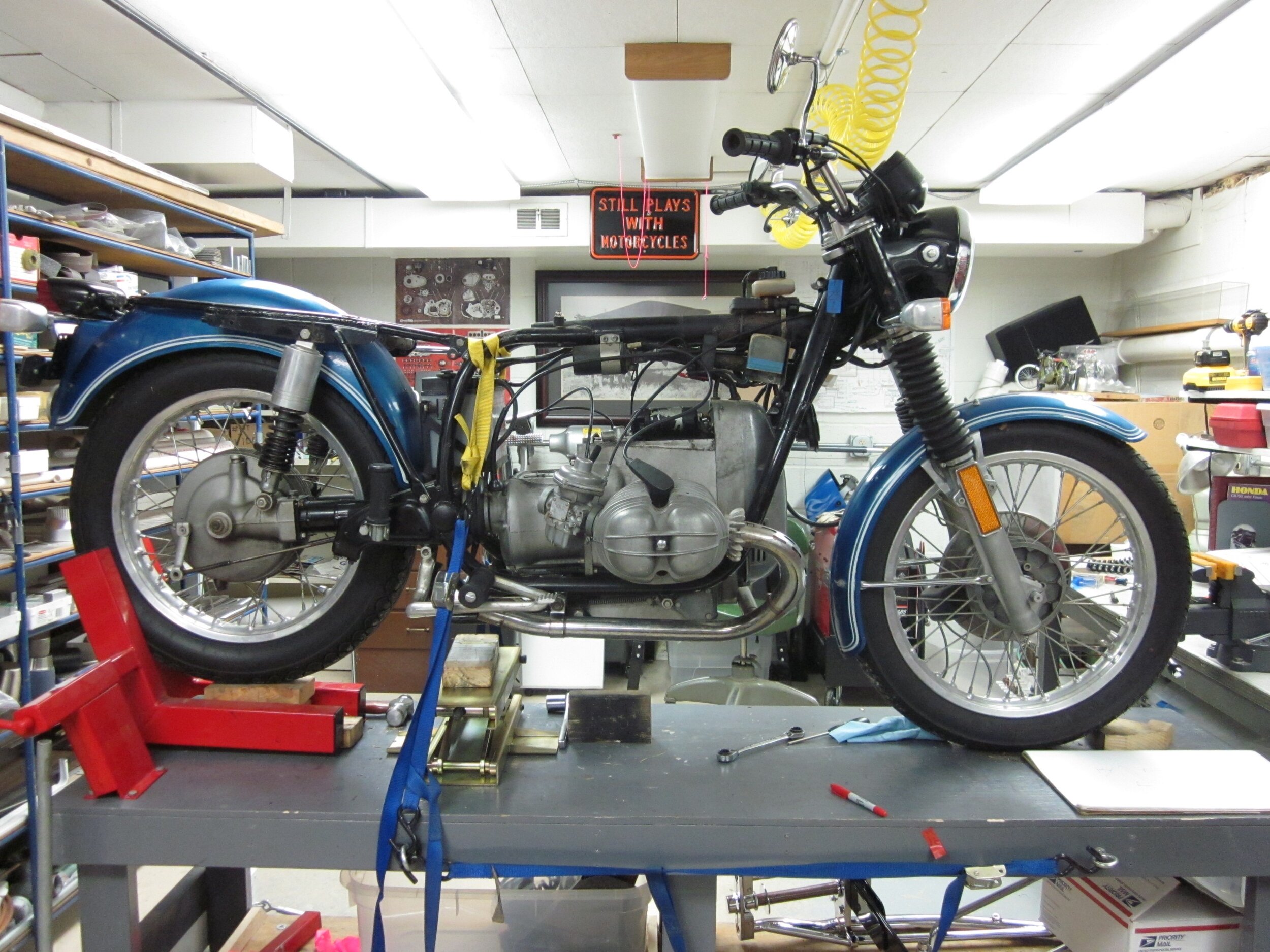
Well the day finally came when enough pieces and parts were attached to each other that I thought the amalgamation had a chance to carry me down the road under its own power.
As you can see, it’s a bit of a Frank-en-bike at this point because nothing is painted or plated and many parts are functional, but not in their final form. The plastic gas tank was from my friend Ray Shaw’s lawn mower. It was in place because even thought I have already discussed the aluminum tank’s fabrication, I actually waited until after the initial beta test rides to make it because if the handling was not good and modifying the frame was needed, I didn’t want to also have to rebuild the tank whose shape is largely dictated by the confines of the space inside the frame’s top and front sections.
On these first rides I started with short loops around the block. I have the option so it’s a left out of the driveway, going uphill, because pushing the motorcycle back to the house would be easier going back downhill!
It was very exciting to be out riding this machine. One of my big challenges was to be critical in my evaluation. I had rose colored glasses on. I often didn’t see things that need correcting because I was consciously or unconsciously filtering information. This filter could reject negative observations because of the realization of how long it would take to fix it, the cost to fix it, or I knew the reason why it is wrong and I didn’t see the work around, or at this point I just wanted to move on with the build.
I did realize the need for changes. One needed change was the front end suspension, which was not moving very much. I started chasing the leaf spring’s rigidity and experimented with different thicknesses and lengths of steel in the “leafs”. At one point I disassembled the axle links and I noticed that they were binding. This assembly came from the supplier as an assembled unit. There is a bolt that each link pivoted on. The bearings in the link were a plastic/nylon type. I was shocked to find the manufacturer used FULLY THREADED bolts for the pivot! So what was happening was the threads in the bolt had dug their way into the plastic/nylon bearing and the link would barely pivot. I replaced the bolts with a standard partially threaded bolt (which allowed the non-threaded portion to ride in the bearing) and cut the threaded end to the proper length. And yes, I also replaced the bearing with a well -proven glass filled nylon type.
This was also the point that I mentioned earlier when I realized the 18” wheel/tires were just not right and the decision was made to change to 19” wheels.

All in all, this beta test riding was very important. I didn’t always get things right the first time. The ride told no lies. However painful reworking things were at this point, it was far less painful than if finished parts had to be thrown away after painting and plating.
One must be willing to sacrifice time and money in “going down a wrong path”. We often fail our way to success.
21. Disassemble
Now that I had ridden the bike, my enthusiasm was recharged like a six year old child after eating an entire box of candy. I needed this energy because it was now time to COMPLETELY disassemble every last part and every wire, so that final finishing work could proceed.
This process started by getting large (18 x 24) zip lock bags and designating a series of shelves to put the bags on. Each zip lock bag had a sequential number and was laid out on the shelves in order of disassembly. There was a corresponding note book referencing the bag numbers that had the necessary notes and reminders for reassembling. 150 pictures were taken before disassembly began (hummm, how did I route those wires?). I kept a dedicated inexpensive camera in the shop for this purpose. Remember, it may be months before you reassemble the machine.
Parts were coming off the motorcycle like clothes on prom night. The finishing work began. Final shaping, filing and sanding were performed. The detail and finish of every piece was very important. Corners needed to be rounded, edges needed to be filed to a radius, that hole in the 1/8 in. thick bracket needed a chamfer on both surfaces, machined pieces of aluminum needed to be sand blasted to look like a casting, every hex bolt needed to be put in the lathe and have its head machined off slightly to have their stamping removed so they had those “machined look” swirls on them.
The finish I chose for every silver colored part would be either its natural aluminum or stainless steel finish, sandblasted aluminum to simulate a cast piece, or, if shiny was needed, the ever so beautiful nickel plating was applied. No chrome.
When all was dismantled and the final finishing completed, parts that needed paint or plating were removed from their zip lock bags and put in corresponding shipping boxes. Then it was off to the painting and plating shops. When the parts come back they were put back in their appropriate zip lock bag.
22. Reassemble
Not to over simplify, this is merely a matter of working your way back along the storage shelves and zip lock bags, referring to your notes and photographs as you go.
23. Down the Road

I did want to say one thing about your following enjoyable years of riding and maintaining. When doing routine maintenance, use your tool kit from the bike. This lets you evaluate how complete the kit is which can be very important when you are faced with an RSE (road side event). Also mark all the tools in the tool roll with a band of colored tape or paint so it can be easily identified if you accidentally put one of them back in your home tool box. If you are afflicted with MBS (multiple bike syndrome) each motorcycle should have its own differentiating color band for its tools.
24. Conclusion
I still have things on my list to do: fish tail exhaust tips and spring mounting the seat are among those items. But this is the good news because I am still getting pleasure from the building as well as the riding.
There are many “thank yous” that need to be said, but four are most appropriate here. Mac Kirkpatrick was nice enough to ask me to consider writing this article. Dain Gingerelli wrote a wonderful article about this bike and Landon Hall, Group Editor of Motorcycle Classics magazine, agreed to publish it in the May/June 2020 issue. Also a big thank you goes out to my wife Lynn, obviously a very special person, for her support of the many hours I spend building in my shop and out riding.
And of course thank YOU, the readers who have kept reading as I have gone on and on about this project of mine. As I said at the beginning of this article, at my core I like to make things and inspire others to make things. I can’t help myself. It’s somewhere in my genes. It is my sincere hope that this article has been an inspiration and a resource for you to make something, even if it’s just one part, for your current motorcycle. You never know where it will lead you.