1914 Harley Davidson Similaria
-
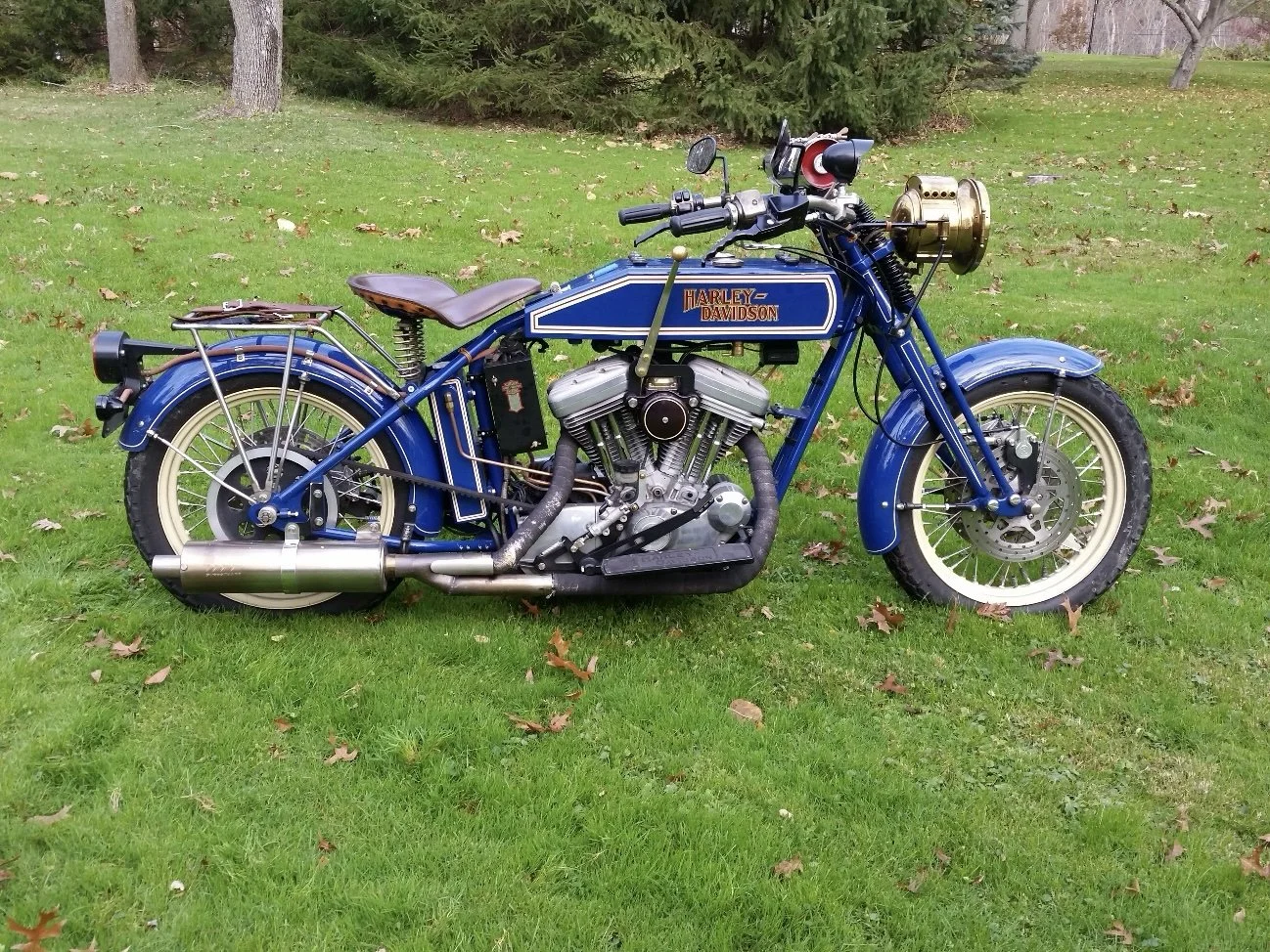
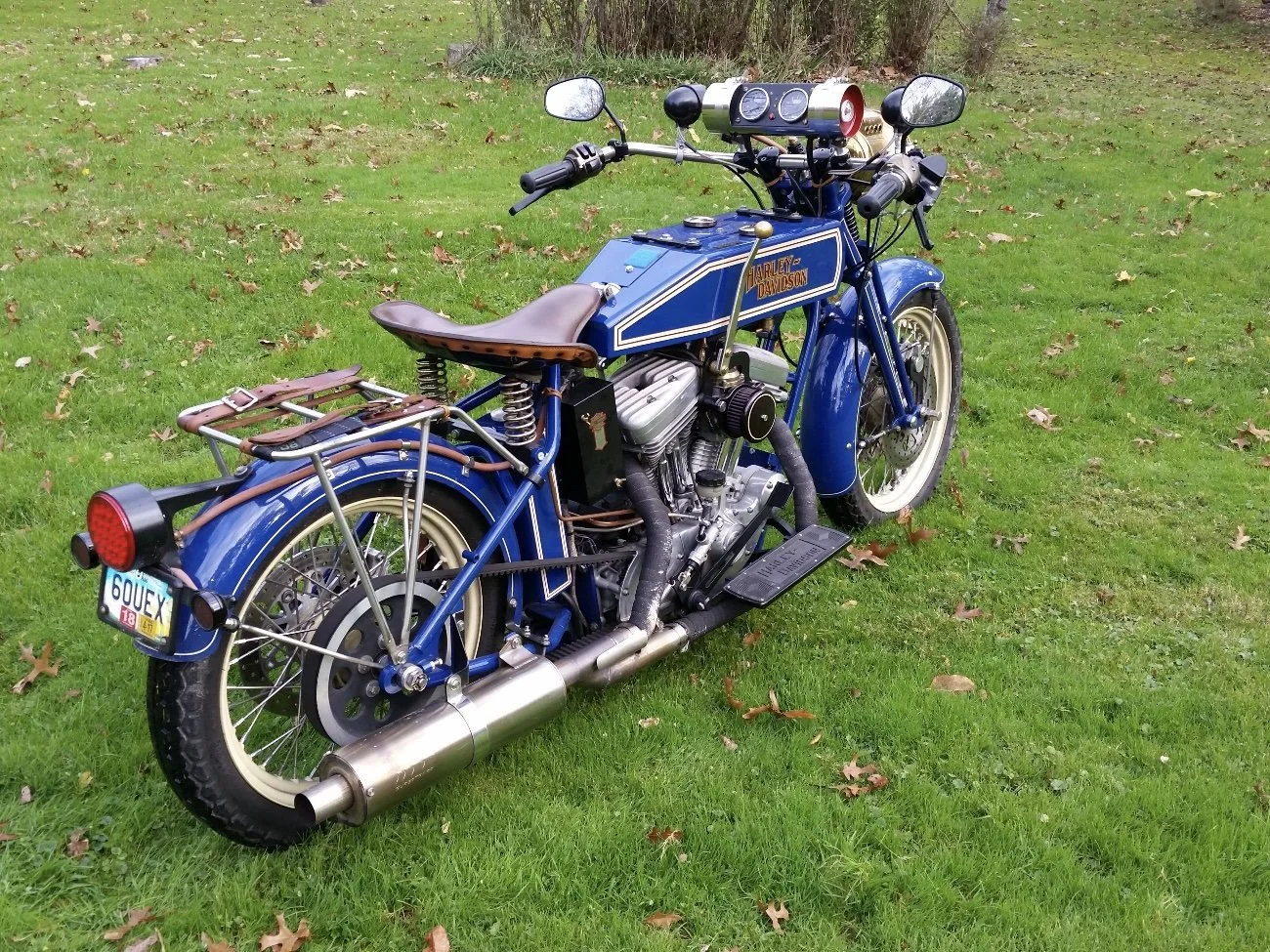
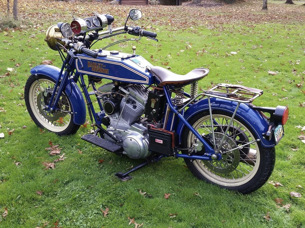
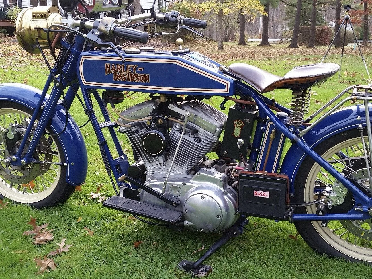
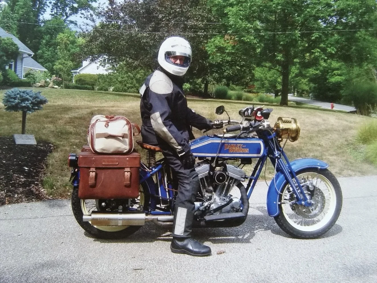
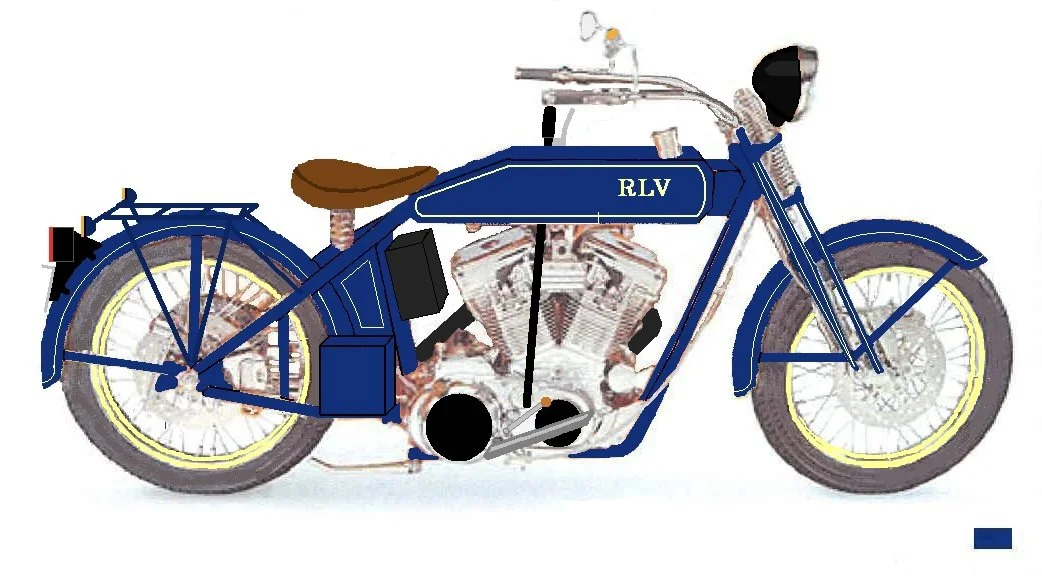
I made this motorcycle to look similar to a circa 1914 Harley-Davidson. It had to be a functional rider capable of running 70 MPH with no strain and with robust electronics capable of powering electrically heated clothing. It took 20 months to build and when the dust settled I had made 195 drawings and 273 fabricated pieces. It has been on the road since August 2011 and as of 2025 it has logging over 19,000 miles. Starting with an Arlen Ness frame, a 1997 Harley Sportster engine (883 cc) was added. The forks were specially made by Paughco, 1” over. Night illumination comes from an original Ford Model “T” B&L brass headlight with a modern H4 headlight unit inside. The engine connects to the rear wheel via a belt drive (remember, the early motorcycles had leather belt drives). It’s a “hard tail” meaning it has no rear suspension. One can shift gears with the hand lever or foot shifter. The front fender “floats” with the wheel. I fabricated a fake acetylene gas bottle on the handlebars that houses the speedometer, tachometer, and indicator lights. Chrome has been eliminated from parts and most silver shiny bits are either nickel plated, aluminum or stainless steel.
-
I was born in 1950 and I saw, from time to time during my impressionable years, the 1910-1920 motorcycles on the road which had such a simple, elegant, graceful look.
-
My MISSION was to make a “Similaria” motorcycle at the intersection of form and function, where great attention would be paid to the details in every part. On antique motorcycles nothing is hidden and every part has a function. The eye picks up the distinctive colors of brass, copper, aluminum, and nickel. My goal was to make a similar motorcycle with that old look, but capable of running continuously at 70 MPH, with good brakes, good lighting, enough electrical power to use heated clothing, and “good to go” for the next 20,000 miles.
My GOALS were to go to the next level of fabricating difficulty from my last project (the “Yamaton”, making an XS650 Yamaha twin look like a Manx Norton). At the beginning of the project I found out to my surprise that this would mean making a pair of mirror image gas tanks and an oil tank, none of which I had ever done before.
What RESOURCES would be needed? I have a lathe, small milling machine, TIG welder, and other needed shop tools for bending, folding and mutilating fabricated parts. What I needed was time, money, raw materials, someone to weld the gas tank pieces after I tack weld them. (I could make all the welds on the gas tank but after thinking about the concept of 5 gallons of gasoline sitting between my legs while I’m going 70 MPH, my preference leaned to letting a pro make the final welds). I would also need someone to do the painting, powder coating, plating, and pin striping.
FEEDBACK on some of my ideas came from friends Ray S. and Doug H. Feedback on how I was doing time wise came from my time line schedule which was monitored regularly. Often I needed to make adjustments with time frames and add new activities.
Twenty months was a long time to keep one’s attention, focus, and enthusiasm for one project so I needed these 4 Guiding Lights to keep me moving.
The Overall Look
-
The flat sides were a must not only because I liked the look but I also figured this would make fabrication easier because I would not have to form rounded pieces with compound curves.
-
The same size wheels and skinny front and rear tires with close fitting fenders.
-
A metal headlight with its Prestolite (acetylene) gas cylinder across the handlebars.
-
A lever on the right side of the gas tank.
-
Rectangle shape.
-
A leather covered tractor style seat.
-
They must be wrap around handlebars.
-
The round cylindrical shaped muffler.
-
Springer front end, hardtail rear end.
-
You can certainly argue that I should have a chain drive BUT first of all, the older Harleys did have a leather belt drive and secondly, with a 45 degree V twin a belt drive does absorb some of the vibration of the engine and, this being a rider, I wanted as pleasant a riding experience as I could get considering my comments above about suspension.
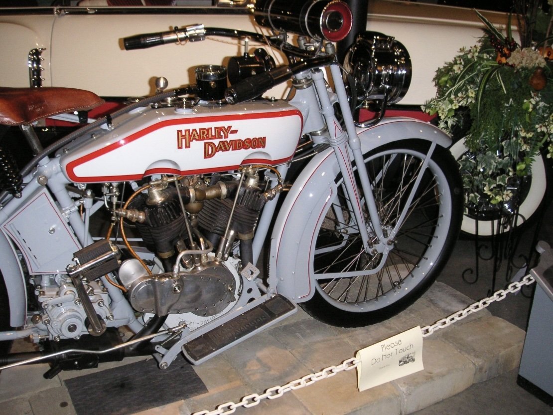
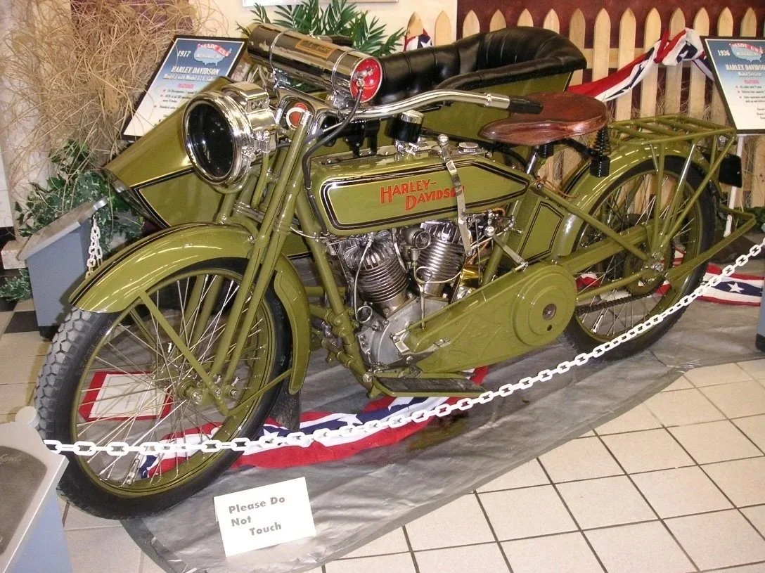
Below are motorcycles that had distinctive features I was looking to have.
-
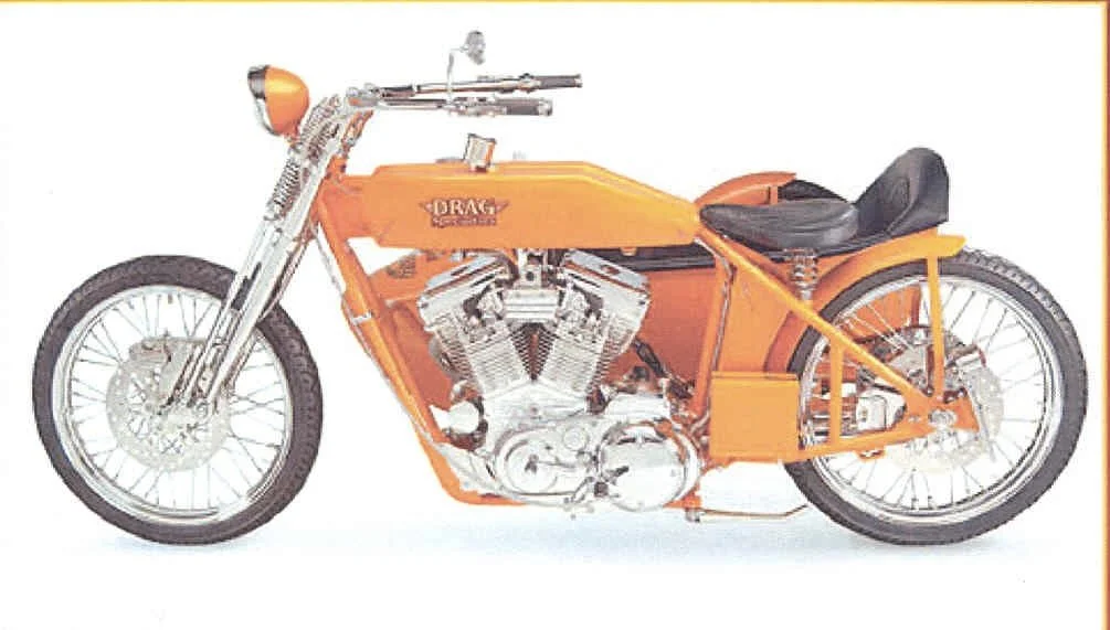
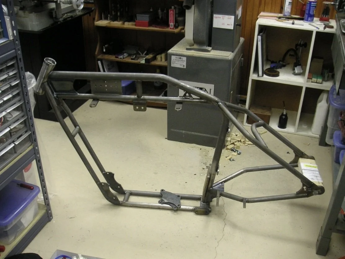
I discovered Arlen Ness made an antique style frame and a picture of the bike using that frame was in the Drag Specialties catalogue.
This (minus the side car) was exactly the overall look I was after.
So I took a picture of it and set to work using “Paint”, the software that came preloaded on my computer. I erased the sidecar, added fenders, a different seat, footboards, an electrical box under the seat, a luggage rack, blue paint, then flipped the image right-to-left, and added a hand shift.
-
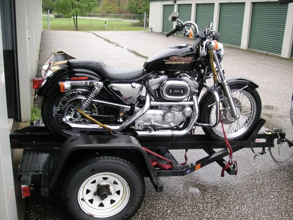
The engine choice was almost a “no brainer”. I wanted a 45 degree V twin and I did not need or want a big twin so the Sportster engine emerged as the answer. I have owned a 2003 883cc Sportster and I have also ridden the 1200cc version and I preferred the 883 due to my perception that it transfers less vibration to the rider. I wanted a 2003 or before because the rubber mounted feature of 2004 and later models, while more comfortable, became more complicated to construct with the rubber mounting of the engine with the attached exhaust pipes. On this rubber mounted engine the exhaust system is connected to the engine in its isolated vibratory envelope and not rigidly tied to the frame directly and I did not want to figure how I would mount that system with the Arlen Ness frame that was not designed for it.
Frame
-
Now I that I had the frame I gave the Arlen Ness folks a call to get the gas tanks and oil tank. That call revealed they no longer made any of the tanks! Oh boy! Was I up to the challenge of making them? I had not done that before. With further thought I realized these tanks had mostly flat surfaces and I did not have to learn the fine art of using an English wheel and a panishing hammer to form them. However I also realized that for the gas tanks, I needed to not only make two gas tanks, but had to make two exact mirror images that mated with each other where they connected to the frame. The oil tank would be a more straight forward fabrication being a basic rectangle.
I decided I was up for the challenge to fabricate these.
Oh I almost forgot, it was then time to get the engine.
SIDE BAR: My preference for all my builds is to get a complete running donor motorcycle and ride it for at least 500 miles before starting the project. This does three things. First, it gives me the assurance that the entire operating system is working properly or it allows me, if necessary, to make any needed changes or repairs BEFORE the build is started which saves me from making repairs around the newly painted/plated surroundings. Secondly, if I go to startup and ride the new creation and something does not work, I have some level of assurance that the parts I am reusing DID work when I put the 500 miles on the donor which limits the trouble shooting process to the changes and additions I have made. Thirdly, I save time by not having to keep picking away at swap meet after swap meet or on eBay looking for parts and hoping they function properly. The running motorcycle has all the parts needed to run. This approach has served me well but yes, there is certainly a price to be paid in dollars for this approach because buying a complete running motorcycle is definitely more costly than buying all the needed bits.
So I bought a donor motorcycle with only 4,065 miles on it.
I did ride it 500 miles and discovered the valve guide seals were shot which was subsequently easily repaired on this stock bike.
-
The Arlen Ness frame was also the obvious choice for the frame. This was great news, not only because of my desire to use the Sportster engine, but also good news because that frame would make provision for the unique way in which the Sportster engine mounts to a frame. The rear of the engine attaches with 4 bolts to a relatively vertical plate on the frame which faces forward. To add to the good news, this frame was designed to give the correct alignment of the transmission’s drive pulley to the rear wheel’s driven pulley. The frosting on the cake was that the Arlen Ness catalogue also showed that they made the two mirror image flat sided style gas tanks that attached to each side to the upper frame tubes. They also made the oil tank.
Next step was to order the frame and get some confirmation on its suitability for my vision.
-
My preference for all my builds is to get a complete running donor motorcycle and ride it for at least 500 miles before starting the project. This does three things. First, it gives me the assurance that the entire operating system is working properly or it allows me, if necessary, to make any needed changes or repairs BEFORE the build is started which saves me from making repairs around the newly painted/plated surroundings. Secondly, if I go to startup and ride the new creation and something does not work, I have some level of assurance that the parts I am reusing DID work when I put the 500 miles on the donor which limits the trouble shooting process to the changes and additions I have made. Thirdly, I save time by not having to keep picking away at swap meet after swap meet or on eBay looking for parts and hoping they function properly. The running motorcycle has all the parts needed to run. This approach has served me well but yes, there is certainly a price to be paid in dollars for this approach because buying a complete running motorcycle is definitely more costly than buying all the needed bits.
-
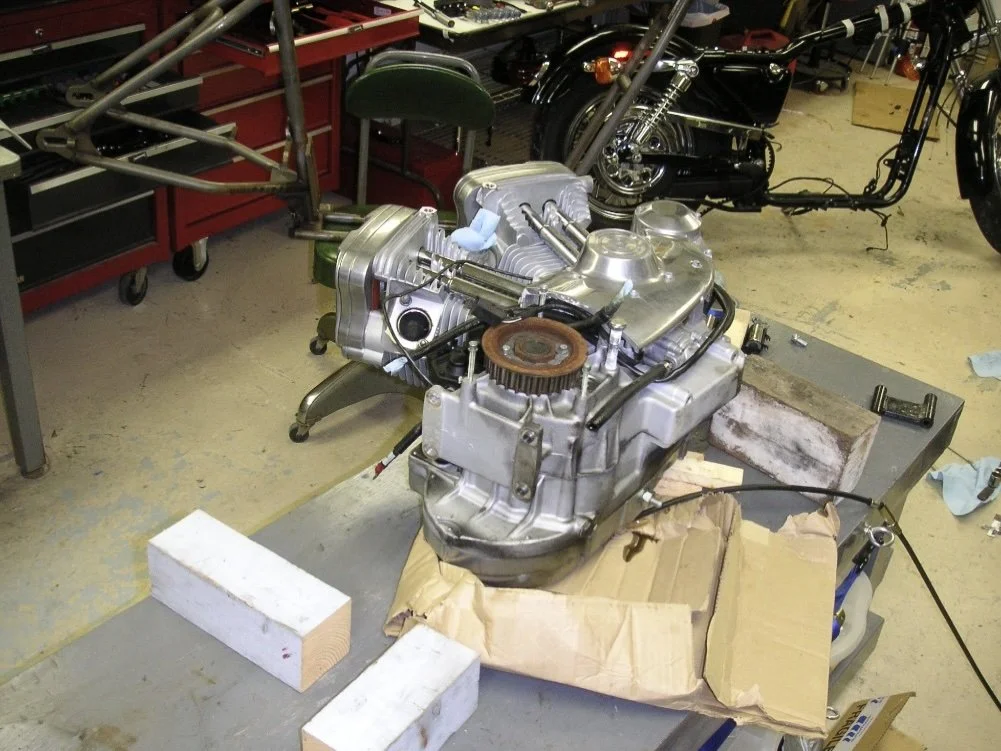
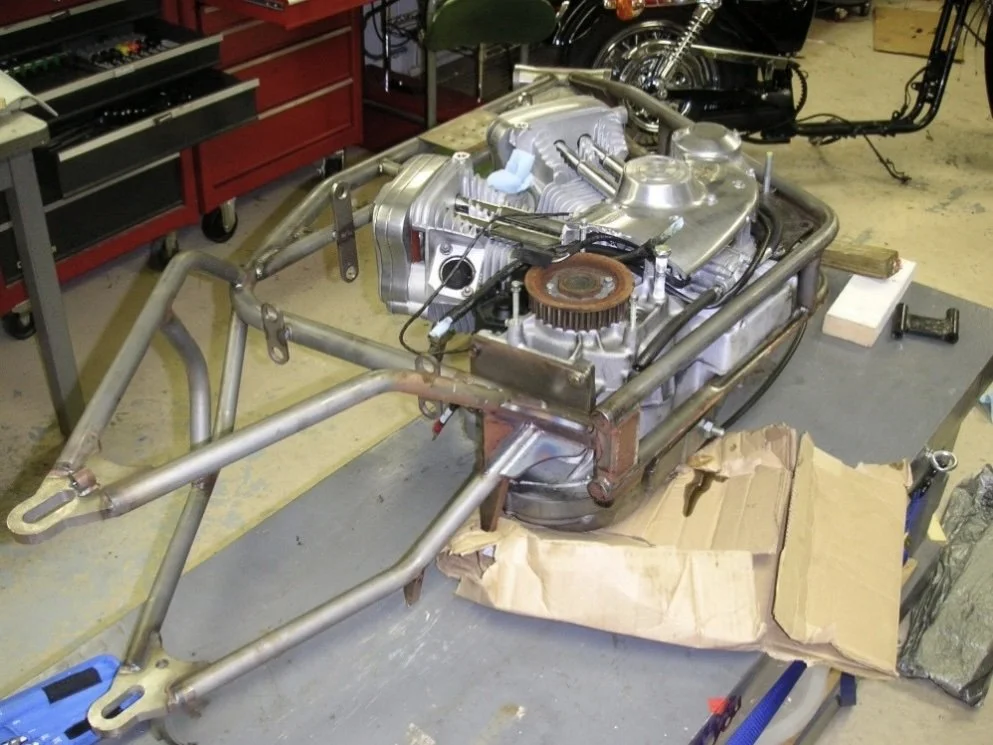
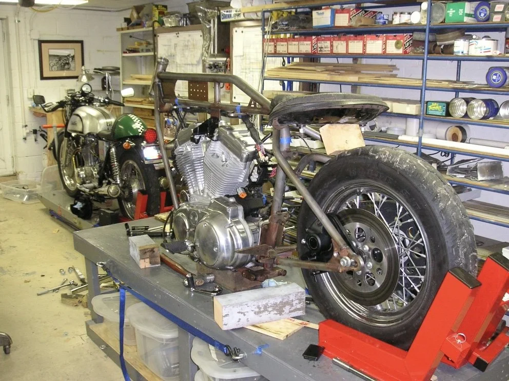
Work then began by removing the engine from the stock bike. All electrical attachments were disconnected along with the gas line, mechanical connections like the throttle and choke cables. Carburetor and exhaust were removed. The object was to get all things removed so that the bike can be rolled over on its side with only the engine bolts holding the engine in place. Then a bunch of wood blocks were cut up to support the engine such that it would remain in place on its side when the engine bolts were removed. Then those bolts were removed and the frame was lifted up off the engine. Then the new frame was lowered over the engine and bolts secured it in the new frame.
Next priority was to get this assembly supported by its wheels. The rear wheel was needed to be mounted with the drive line figured out. If a chain was to be used the alignment of the engine and the wheel sprockets needed to be figured out. The distance between these two sprockets is not so critical because chains are available in any length. However, as I had mentioned, my plan was to use a belt drive but these seemed to be available in a limited number of lengths. Fortunately Arlen Ness had this figured out with the position of the engine and the slots for the rear axle. I did make up some custom axle spacers to get the rear wheel and its belt pulley aligned with the engine’s pulley which put the wheel centered in the frame.